ApplicationNote
InterfacingtoaGraphicsModulewithaToshiba
T6963CController
Page1
Introduction:
FunctionalDescription:
Schematic:
TheToshibaT6963CLCDcontrollerisoneofthemostpopularcontrollersforuseinsmallgraphics
displays.ForthisreasonitisusedinanumberofLCDmodulesfrom128x128to 240x128 pixels.
Thisclassofmoduleismostcommonlyusedtodisplayamixtureoftextand graphics in samall
devicesandinstruments.Itisusuallyinterfaceddirectlywithanembedded8-bit microprocessor.
Thisapplicationnotedescribestheuseofthiscontrollerwithanumberof graphics modules.
Theexampleusedhereisbasedonan8-bitIntelI8051microcontroller but applies to almost any
micro-controller.
TheT6963Cusesasimple8-bitdatabustotransferallinstructionsanddatatoandfromthe
display.Afterpowerisappliedahardwareresetisissued.Thecontrollermustthenbeinitialized
withaseriesofcommandstosetupthevariousmodesandoptionsavailabletotheuser.Once
initializedthedisplayisreadytoacceptthedatatobedisplayed.Thisdatacanbeintheformof
bit-mappedgraphicaldataortextdatainpseudoASCIIformat.Theinternalcharactergeneratoris
biasedat-20h.whichmeanstheusermustsubtract20hfromtheASCIIcodebeforesendingitto
thedisplay.
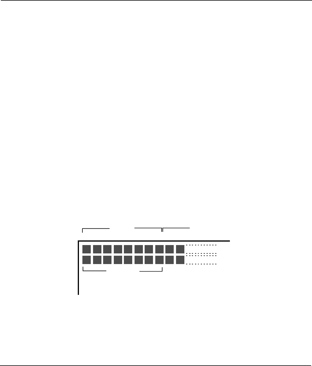
Inthebit-mappedmodeeachbyteofdatarepresents8pixelsonthedisplay.SeeFigure#1.Text
datacanbewritteninpseudoASCIIformatandwillbedisplayedasa5x7dotcharacter.The
graphicalandtextdataarewrittentoseparate,userassigned,areas,orpages,inthedisplayRAM
withinthedisplaymodule.Theusercanthenchooseoneofthreewaystomixthetextand
graphicspagesonthedisplayorthetextorgraphicspagecanbedisplayedalone.
The80C51microprocessorisconnectedtotheLCDcontrollerchipviaparallelI/Oportsinthis
example.Itcouldalsobeconnectedtotheprocessor'sdatabusandbemappedintothe
processor'sdatamemoryarea.Seefigure2.
D0
D1
D2
D3 D4 D5
D6
D7 D0 D1
1BYTE
ST
17BYTE
TH
2BYTE
ND
Figure#1Memorymapofa128x128display
