


19
Operations
18
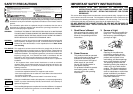
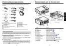
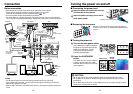
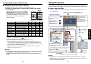
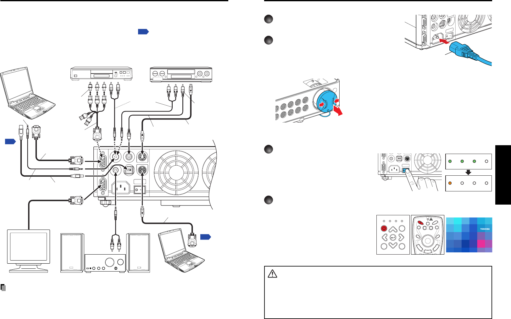
■ Connecting the power cord
1
Insert the power cord connector into the
AC IN socket of the projector.
2
Insert the power cord plug into a wall or
other power outlet.
■ Removing the lens cover
Be sure to remove the lens cover when the power is
turned on. If it is left on, it could become deformed due
to heat.
■ Turning the power on
1
Turn on the main power switch
Then, following three green indicators
will come on for several seconds: ON,
TEMP, and LAMP. Next, the ON
indicator will change to orange,
indicating standby mode.
2
Press the ON/STANDBY
button.
The power turns on, and the following
3 green indicators light: ON, LAMP,
and FAN. After a moment, the start-up
screen appears.
CAUTION
• Do not look into the lens during operation. Doing so could damage your vision.
• Do not block the air intake or exhaust. Doing so could cause a fire due to internal
overheating.
• Do not place your hands, face, or other objects near the air exhaust. Doing so could
cause burns, deform/break the object.
Turning the power on and off
Start-up screen
D
R
A
G
R
-
C
L
I
C
K
L
-
C
L
I
C
K
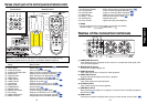
AUTO
KEYSTONE
AUTO
SET
PAG E
UP
PAG E
DOWN
FREEZE
MUTE
CALL
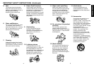
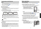
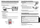
ON/STANDBY
LASER
ON/STANDBY INPUT
MENU
ON LAMP TEMP FAN
AUTO KEYSTONE AUTO SET
VOL.
+
VOL.
-
Control panel
Remote
Control
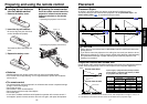
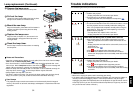
COMPUTER INMONITOR OUT
S
-V
ID
E
O
V
ID
E
O
A
U
D
IO
IN
A
U
D
IO
O
U
T
U
S
B
C
O
N
T
R
O
L
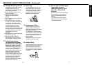
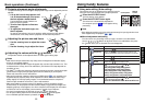
Before connection
• Read the owner’s manual of the device to be connected to the projector.
• Some types of computer cannot be used connected to this projector.
Check for an RGB output terminal, supported signal
p.36
, etc.
• Turn off the power of both devices before connection.
• The figure below is a sample connection. This does not mean that all of these devices
can or must be connected simultaneously. (Dotted lines mean items can be exchanged.)
Note
• The AUDIO IN terminal is common among all the devices for input terminal.
• On the AUDIO OUT terminal, L and R mixture audio signal (monaural) that volume is
adjusted by a projector is output.
• When a plug is inserted to the AUDIO OUT terminal, the projector's speaker outputs no
sound.
Connection
S-VIDEOVIDEOAUDIO IN
AUDIO OUT USB
COMP
U
MONITOR OUT
CONTROL
ON LAMP TEMP FAN
ON LAMP TEMP FAN
(Green) (Green) (Green) (Off)
(Orange) (Off) (Off) (Off)
S-VIDEOVIDEOAUDIO IN
AUDIO OUT USB
COMPUTER INMONITOR OUT
CONTROL
Computer
CRT monitor, etc.
To audio
output
Audio cable
(for computer)
(supplied)
To RGB
output
Control cable
To RS-232C
terminal
Computer (for control)
RGB cable
(supplied)
To Y/CB/CR output
Green (Y), Blue (CB),
Red (CR)
Yellow
(to video output)
To audio
output
White (L)
Red (R)
VCR
S-Video cable
(not supplied)
Video cable
(supplied)
To S-Video
output
To audio
output
White (L)
Red (R)
Monitor cable
Mini D-sub 15P-BNC
(not supplied)
Audio cable
(supplied)
DVD player
Conversion
adapter
BNC-pin
(not supplied)
p.38
p.30
Audio system, etc.
USB cable
(supplied)
To audio
input
White (L)
Red (R)
To USB
port
(Supplied) Power cord connector