


About the Redundant 10BaseFL Slide-In Card:
The TRANSITION Networks, P/N E-FL/RED-SIC, is a slide-in card that provides a
reliable backup feature for the fiber optic connection. The fiber optic cable can
extend the transmission distance up to 6,600 feet (2 kilometers).
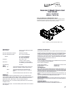
Figure 1 Crossview of the Fiber Redundant Slide-In Card
Redundant 10BaseFL Slide-In Card
User’s Guide
Model #: E-FL/RED-SIC
Manual #: 7339.B 5/94
Specifications:
Fiber Connection: ST type connectors (SMA type available
upon request)
Fiber Optic Cable Maximum Distance: 6,600 feet (2 kilometers)
Fiber Optic Cable Recommended: 62.5 / 125 µm multimode fiber
Optional 100 / 140 µm multimode fiber
85 / 125 µm multimode fiber
50 / 125 µm multimode fiber
Dimensions: 5.50” x 3.00” x 1.00”
(13.97cm x 7.62cm x 2.54cm)
Environment: 0–70 degrees C, 5%–90% humidity
non-condensing, 0–10,000 feet altitude
Limited Warranty: Two years
LED's:
Fiber Port: Link - Lit green LED indicates the Slide-In Card is receiving link
pulsed from a 10Base FL (or FOIRL) compliant device.
Enable - Lit green LED indicates current link between fiber
connections. Only the active enable (1 or 2) LED will
appear.
Fault - Lit red LED indicates a break in both fiber links 1 and 2.
SQE Switch:
The SQE (Signal Quality Error) heartbeat selection jumper can be positioned ON to
enable the SQE or positioned OFF to disable the SQE. The SQE jumper is located on top
of the transceiver printed wiring circuit board. The transceiver SQE is set to the OFF
position at the factory. (Refer to Figure 1 on the front page of this guide.)
SQE Enable Position (ON): The transceiver SQE is positioned ON when connected to a
workstation or DTE.
SQE Disable Position (OFF): The transceiver SQE is positioned OFF when connected to a
Hub or Repeater.
Installation Considerations:
Personnel can hot swap, install or remove a Slide-In Card with the hub unit power
The Slide-In cards can only be installed one way, with the components facing up.
Carefully guide the Slide-In Card along the card guides, until the Slide-In Card flat
connector and internal backplane meet. Carefully seat the connector into the
backplane slot. Firmly push the card into the slot until the Slide-In Card face plate
is flat against the back of the hub frame. Tighten the thumbscrews of the installed
Slide-In Card into the threaded holes on the hub unit.
Technical Support:
For more information about this product or other TRANSITION Networks products
your local TRANSITION Networks distributor.
Direct numbers are listed below:
TN Main Phone Numbers: (800) 325-2725 or (612) 941-7600
TN Technical Support Number: (800) 260-1312
TN Fax Number: (612) 941-2322
FCC Regulations:
Note: This equipment has been tested and found to comply with the limits for a C
digital device, pursuant to Part 15 of the FCC Rules. These limits are designed to p
reasonable protection against harmful interference when the equipment is operated
commercial environment. This equipment generates, uses, and can radiate radio f
quency energy and, if not used in accordance with the
instruction manual, may cause harmful interference to radio communications. Op
of this
equipment in a residential area is likely to cause harmful interference in which cas
user will be required to correct the interference at his own cost.
Canadian Regulations:
Note: This digital apparatus does not exceed the Class A limits for radio noise for
apparatus set out on the radio interference regulations of the Canadian Departmen
Communications.
Trademark Notice:
Ethernet is a registered trademark of the Xerox Corporation, Inc.
TRANSITION Networks is a trademark of TRANSITION Networks, Inc.
Re
P/N