


1111 W. 35th Street • Chicago, IL 60609 USA
Customer Support: (773) 869-1234 • www.tripplite.com
Owner’s Manual
Connecting an SUPDU001 to the Output of a SmartOnline
™
SU6K, SU10K, SU6000RT3U or SU10KRT3U
Important Safety Instructions! Save These Instructions!
WWAARRNNIINNGG!!
Before connection, make sure that your entire SmartOnline system is OFF
(including transformer modules, where applicable), that all
input and output breakers are
switched OFF and that the system is not connected to AC power.(See SmartOnline Owner’s
Manual.)
WWAARRNNIINNGG!!
SUPDU001 installation and wiring should only be made by a qualified electrician
observing all applicable local, state and national electrical codes and requirements.
• Remove screws and open SUPDU001 case.
• Remove any one of the eight knockouts (either ½ or ¾ inch) around the edge of
SUPDU001 case. Attach a user-supplied conduit connector.
• Attach a second user-supplied conduit connector to the terminal box cover of the
SmartOnline UPS System.
• Connect user-supplied flexible,armored-cable conduit between the SUPDU001 and the
SmartOnline UPS System terminal box.
• Run user-supplied wire through the conduit and make appropriate connections inside the
SUPDU001 and inside the SmartOnline UPS System terminal box.
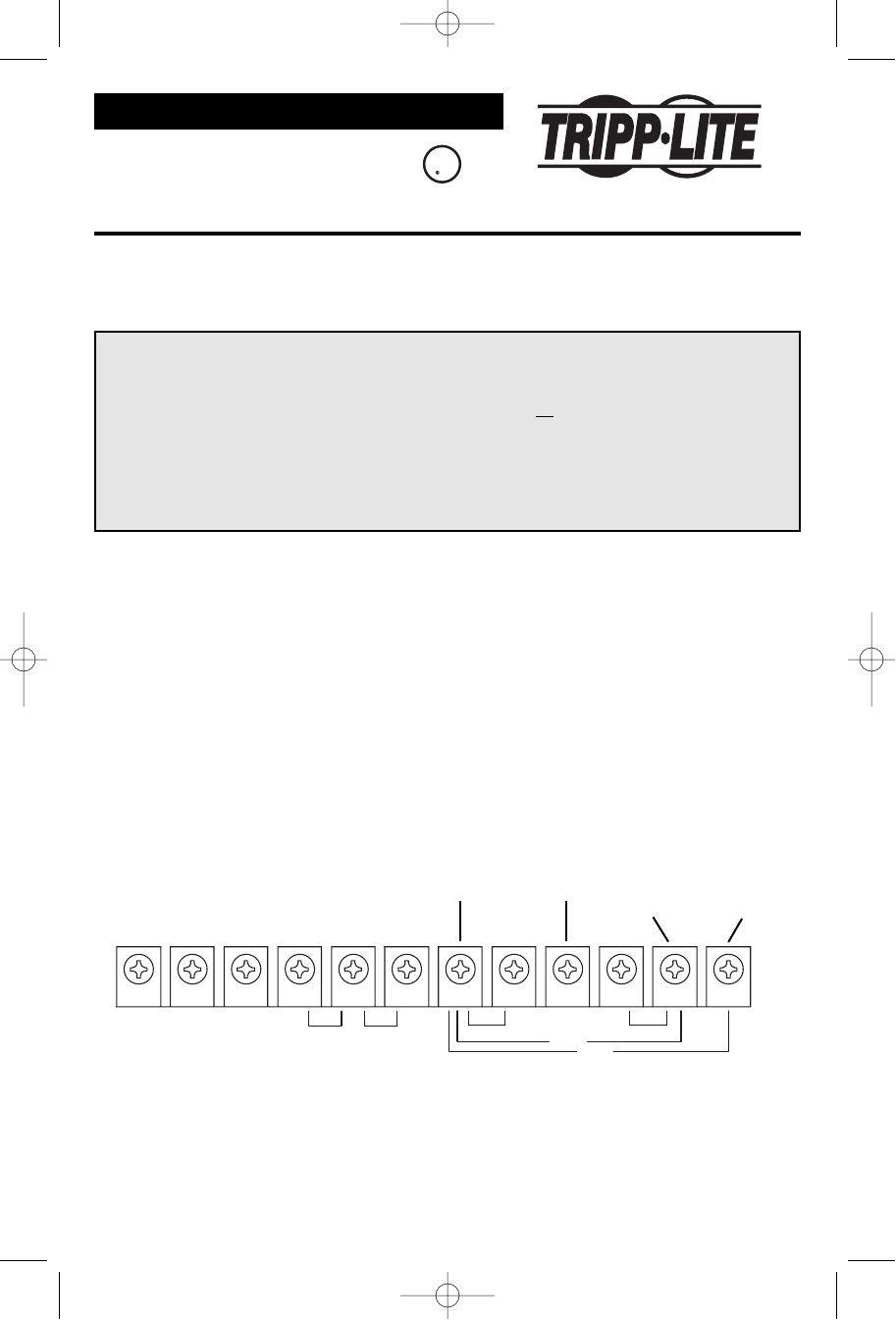
• Connect the colored wires to the SmartOnline’s terminal block as shown below. The brown
wire can be connected for either 240V output or 208V output.Note: the desired output
voltage MUST match the SmartOnline’s output voltage.(See SmartOnline Owner’s Manual.)
L2
L1 G
AC INPUT
208V
240V
INPUT
VOLTAGE SELECT
120V 120V
G
240V
208V
L3
N
N
L2
L1
Copyright ©2003 Tripp Lite.All rights reserved.SmartOnline™ is a trademark of Tripp Lite.
200301143 93-2114
Blue
Green Brown
(240V)
Brown
(208V)
or
SUPDU001
Wiring Instructions
CUS
U
L
UL1788 Listed
UPS Accessory
200301143 93-2114 SUPDU001 Owner’s Manual Revision.qxd 3/19/2003 11:46 AM Page 1