


2
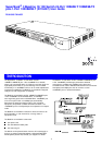
MDI Switch
This switch affects port 24 only:
3
Display Function Switch
This switch affects the Status LEDs described in 4 and 5:
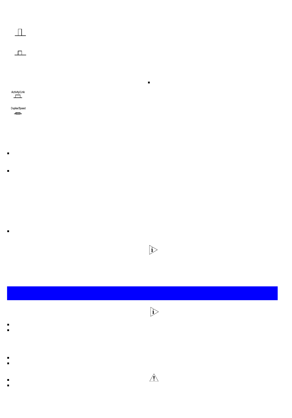
4
Activity/Duplex Status LEDs
The first (top) and third row of LEDs, which are colored yellow,
show the activity or duplex status of the related ports:
When the Display Function switch is out (its normal position),
these LEDs show the activity of each port. The LED flashes
when packets are received or transmitted on the port.
When the Display Function switch is pressed in, these LEDs
show the duplex status of each port:
5
Link/Speed Status LEDs
The second and fourth (bottom) row of Status LEDs, which are
colored green, show the link or speed status of the related ports:
When the Display Function switch is out (its normal position),
these LEDs show the link status of each port:
When the Display Function switch is pressed in, these LEDs
show the speed status of each port:
6
Power/Self Test LED
The Power/Self test LED lights green when the unit is powered on
and ready for use.
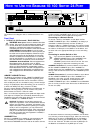
Rear Panel Connections
7
Power Supply
The Baseline 10/100 Switch 24 Port 10BASE-T/100BASE-TX plus
1-Port 1000BASE-T automatically adjusts to the supply voltage.
Only use the power cord that is supplied with the unit.
8
Socket for Redundant Power System (RPS)
Only connect a 3Com SuperStack 3 Advanced RPS (3C16070,
3C16071, 3C16071A or 3C16071B) to this socket. An
appropriate power module and cable is required. The connector
on the Baseline 10/100 Switch 24 Port 10BASE-T/100BASE-TX
plus 1-Port 1000BASE-T is a Type 2 socket. For details, follow the
installation instructions in the guides that accompany the
Advanced RPS and the power module.
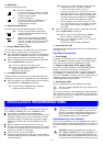
9
Self-adhesive Pads
The unit is supplied with four self-adhesive rubber pads.
You do not need to apply the pads if you intend to rack
mount the unit.
If the unit is to be part of a free standing stack, apply the pads to
each marked corner area on the underside of the unit. Place the
unit on top of the lower unit, ensuring that the pads locate with
the recesses of the lower unit.
Positioning the Switch
When deciding where to position the Baseline 10/100 Switch 24
Port 10BASE-T/100BASE-TX plus 1-Port 1000BASE-T ensure:
It is accessible and cables can be connected easily.
Cabling is away from sources of electrical noise. These include
lift shafts, microwave ovens, and air conditioning units. Elec-
tromagnetic fields can interfere with the signals on copper
cabling and introduce errors, therefore slowing down your
network.
Water or moisture cannot enter the case of the unit.
Air flow around the unit and through the vents in the side of
the case is not restricted (3Com recommend that you provide
a minimum of 25mm (1in.) clearance).
The air is as free from dust as possible.
Temperature operating limits are not likely to be exceeded. It
is recommended that the unit is installed in a clean, air condi-
tioned environment.
It is always good practice to wear an anti-static wrist
strap when installing network equipment, connected to a
ground point. If one is not available, try to keep in con-
tact with a grounded rack and avoid touching the unit's
ports and connectors, if possible. Static discharge can
cause reliability problems in your equipment.
Rack Mounting or Free Standing
The unit can be mounted in a 19-inch equipment rack using the
Mounting Kit. Refer to “Mounting Kit Instructions” on page 4, or
it can be free standing. Do not place objects on top of the unit or
stack.
CAUTION: If installing the Baseline 10/100 Switch 24
Port 10BASE-T/100BASE-TX plus 1-Port 1000BASE-T in a
free standing stack of different size SuperStack 3 units,
the smaller units must be installed above the larger ones.
Do not have a free standing stack of more than six units.
Out Port 24 is an MDIX port.
It can be connected to a device with an MDI
port (such as a workstation) using a normal
‘straight through’ TP cable.
In Port 24 is an MDI port.
It can be connected to an MDIX port on a
device (such as a hub) using a normal
‘straight through’ TP cable.
Out This is the normal position of the switch.
The Status LEDs show the Activity and Link
Status of each port.
In When the switch is pressed in, the Status
LEDs show the Duplex and Speed Status of
each port. The switch returns to the out posi-
tion when released. This switch does not
affect port 25.
On The port is operating in full duplex mode.
Off Ports 1 to 24: If the link is established, the port is
operating in half duplex mode.
Port 25: No link is present.
On The link has been established and the segment
attached to the port is functional.
MDIX
MDI
Off The link has not been established. Either nothing is
connected to the port, or there is a problem:
■
Check that the attached device is powered on.
■
Check that the cable is the correct type and is not faulty.
If the LED is off for port 24, check the setting of the
MDI switch. Refer to 2. Try toggling the MDI switch.
If the port is connected to another unit’s MDI/MDIX
port, check the other unit’s MDI switch position.
If these checks do not identify the cause of a prob-
lem, it may be that the unit or the device connected
to the port is faulty. Contact your supplier for fur-
ther advice.
On Ports 1 to 24: The port is operating at 100Mbps.
Port 25: The port is operating at 1000 Mbps
Off Port 1 to 24: If the link is present, ports 1 to 24 are
operating at 10Mbps.
Port 25: The link has not been established.
I
NSTALLATION
R
ECOMMENDATIONS
3