


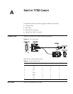

78 APPENDIX A: SWITCH 7750 CABLES
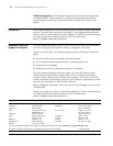
Figure 45 The AUX Cable
Table 54 lists the AUX cable pin-outs.
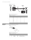
Electrical Port
Connector
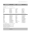
Figure 46 illustrates the RJ-45 connector.
Figure 46 The RJ-45 Connector
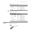
Table 55 lists RJ-45 MDI port pin-outs.
Table 54 AUX Cable Pin-outs
RJ-45 Signal Direction DB-25 DB-9
1 RTS ---> 4 7
2 DTR ---> 20 4
3 TXD ---> 2 3
4 CD <--- 8 1
5 GND --- 7 5
6 RXD <--- 3 2
7 DSR <--- 6 6
8 CTS <--- 5 8
Enlarged B side
Enlarged B side
Enlarged A side
Enlarged A side
Enlarged C side
Enlarged C side
DB25 Male
DB25 Male
Label
Label
DB9Male
DB9Male
8P8C Plug
8P8C Plug
Table 55 RJ-45 MDI Port Pin-outs
Pinout 10BASE-T/100BASE-TX 1000BASE-T
Signal Function Signal Function
1 Tx+ Send data BIDA+ Send data to direction A
2 Tx- Send data BIDA- Receive data from direction A
PIN #8
PIN #1