


14 C
HAPTER
1: I
NTRODUCING
THE
S
WITCH
1100
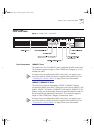
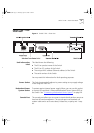
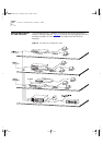
LEDs
Ta bl e 3
lists the LEDs visible on the front of the Switch, and their states
according to color. For information on using the LEDs for problem solving,
see “
Checking for Correct Operation” on page 29.
Table 3
LED behavior
LED Color Indicates
TCVR Yellow Port 1 is a Transceiver Module fitted to the rear of the
Switch.
Off Port 1 is operating as a 10BASE-T port.
Port Status LEDs
Packet Yellow Packets are being transmitted/received on the port.
Off No packets are being transmitted/received on the port.
Status Green A link is present, and the port is enabled.
Green flashing A link is present, but the port is disabled.
Off No link is present.
Expansion Module Port Status LEDs
Packet Yellow Packets are being transmitted/received on the
Expansion Module port(s).
Off No packets are being transmitted/received on the
Expansion Module port(s).
Status Yellow A valid Expansion Module is installed.
Yellow flashing An unrecognized Expansion Module is installed.
Off No Expansion Module is installed.
Unit LEDs
1–8 Green The Switch forms a stack with other Switch units; the
LED indicates the position of the Switch in the stack
and that a link is present. Note that although there are
eight LEDs, only four Switch units can be stacked at
present.
Off The Switch is stand-alone.
Power/Self Test LED
Green The Switch is powered-up.
Green flashing The Switch is either downloading software or is
initializing (which includes running a Power On Self
Test).
Yellow The Switch has failed its Power On Self Test.
Off The Switch is not receiving power.
16950ua.bk Page 14 Thursday, April 29, 1999 1:28 PM