


WARNING: Installation and removal of the Module must
be carried out by qualified personnel only. Before installing
the Module into a unit, you must first disconnect the unit
from the mains power supply. For full safety instructions,
refer to the user guide that accompanies the unit.
AVERTISSEMENT: Confiez l'installation et la dépose de ce
Module à un personnel qualifié. Avant d'installer ce
Module dans un groupe, vous devez au préalable
débrancher ce groupe de l'alimentation secteur. Pour
prendre connaissance des consignes complètes de sécurité,
consultez le guide utilisateur qui accompagne ce groupe.
VORSICHT: Die Installation und der Ausbau des Moduls
darf nur durch Fachpersonal erfolgen. Vor dem Installieren
des Moduls in einem Gerät muß zuerst der Netzstecker
des Geräts abgezogen werden. Vollständige
Sicherheitsanweisungen sind dem Benutzerhandbuch des
Geräts zu entnehmen.
WARNING: When the Module is inserted into the switch,
the captive screws securing the Module must be tightened
with a suitable tool. Keep the blanking plate and the
fixings in a safe place. If you remove the Module at any
time, you must then replace the blanking plate.
AVERTISSEMENT: Quand le Module est inséré dans le
commutateur, visser le module, en le securisant fortemant
avec un outil adapté. Conservez la plaque d'obturation et
les fixations en lieu sûr. Si vous retirez le Module à tout
instant, vous devez alors replacer la plaque d'obturation.
VORSICHT: Beim Einsetzen des Moduls in dem Switch
sind die unverlierbaren Schrauben mit einem passenden
Werkzeug festzuziehen. Die Distanzplatte und die
Befestigungselemente an einem sicheren Ort aufbewahren.
Beim Austausch des Moduls ist auch die Distanzplatte zu
ersetzen.
Handling the Module
The Module can be easily damaged by electrostatic
discharge. To prevent damage, observe the following:
Always wear an anti-static wristband connected to a
suitable earth point.
Do not remove the Module from its packaging until
you are ready to install it into a Switch.
Do not touch any of the pins, connections or
components on the Module.
Handle the Module only by its edges and front panel.
Always store or transport the Module in anti-static
packaging.
CAUTION: The Interconnect Module is not hot-swappable
or hot-insertable. Always make sure that the Switch is
powered down and disconnected from the mains before
installing or removing a Module. Use the following
instructions when installing or removing a Module.
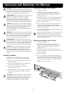
Installing the Module into a Switch
To install the Module:
1 Ensure that the power supply and the backbone
connection cables are disconnected from the Switch.
Always wear an anti-static wristband connected to a
suitable earth point.
2 Undo the three screws securing the blanking plate at the
rear of the Switch using a suitable screwdriver. Do not
remove any other screws from the rear of the Switch.
3 Remove the blanking plate.
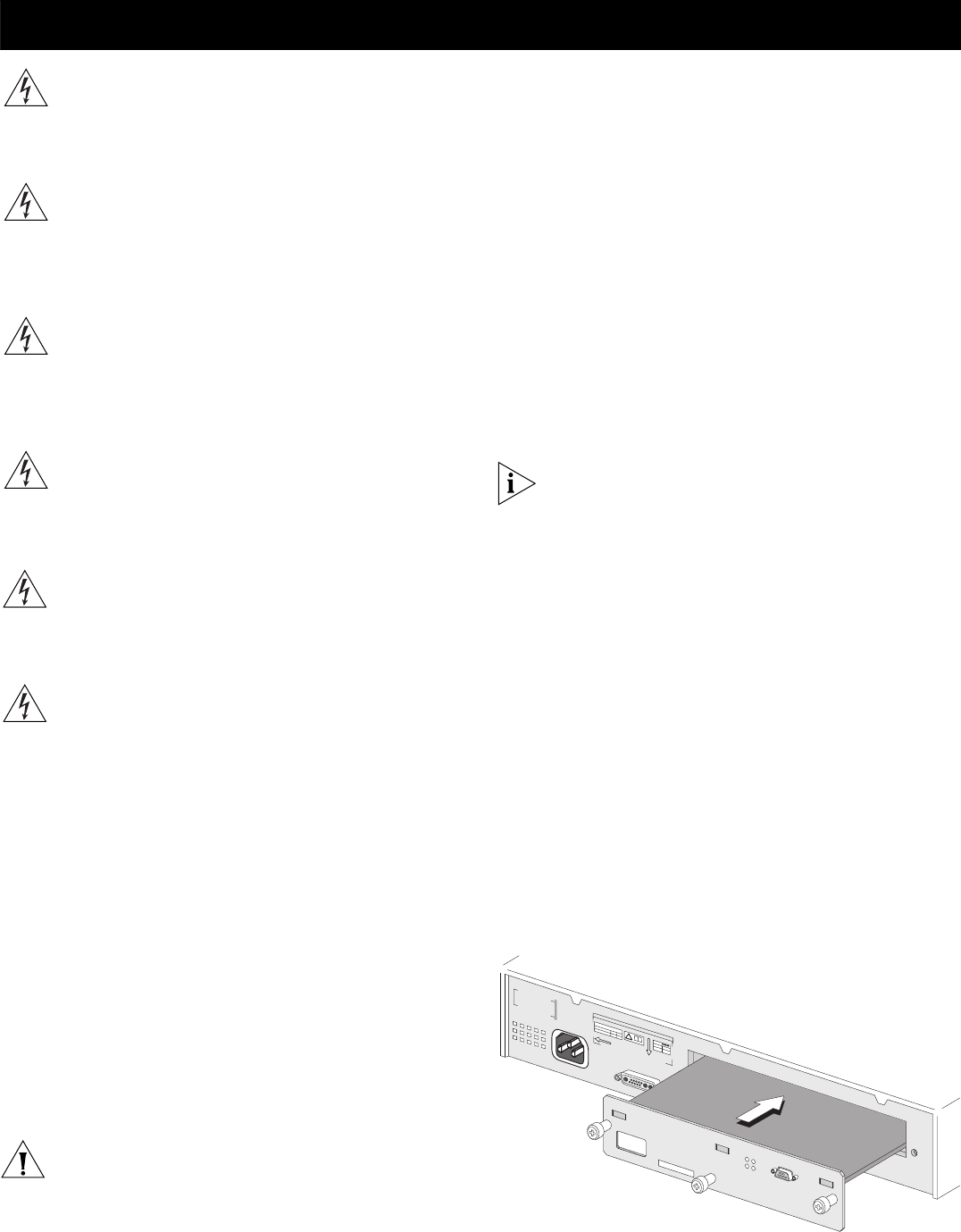
4 Hold the Module so that the text on the front panel is
upright and insert it into the Switch, ensuring the
connectors are fully engaged (see Figure 2). Make sure the
Module is pushed fully in.
5 Secure the Module by tightening the three captive screws
with a suitable screwdriver.
Keep the blanking plate and screws in a safe place. If you
remove the Module at any time, you must replace the
blanking plate to prevent dust and debris entering the
Switch. Replacing the blanking plate will also help circulate
cool air through the Switch.
Removing the Module from a Switch
To remove the Module:
1 Ensure that the power supply and the backbone
connection cables are disconnected from the Switch.
Always wear an anti-static wristband connected to a
suitable earth point.
2 Undo the three captive screws on the Module with a
suitable screwdriver. Do not remove any other screws from
the rear of the Switch.
3 Remove the Module.
4 If you are not fitting another Module immediately, you
must replace the blanking plate to ensure that dust and
debris do not enter the Switch. Replacing the blanking
plate will also help circulate cool air through the Switch.
Figure 2 Installing the Module
INSTALLING AND REMOVING THE MODULE
!
!
S/N
:
XXX
X
/7
XXXXXXXX
X
S/N: XXXX/7XXXXXXXXX
3C17716XRN Interconnect M
odule
3C17716XRN Interconnect Module
Console
(m
ax) 19200,8,1,N
Console
(max) 19200,8,1,N
U
n
it 1
Unit 1
U
n
it 2
Unit 2
A
c
tiv
ity
Activity
S
ta
tu
s
Status
3C17700
M
A
C
A
d
d
r: X
X
X
X
X
X
X
X
X
X
X
X
Sw
itch 4900
S
e
ria
l
N
o
X
X
X
/X
X
X
X
X
X
X
X
X
X
S
U
P
P
L
Y
D
A
TA
V-
9
0
- 2
4
0
H
z
5
0
/6
0
A
INPUT
V
27
A
M
a
x
12
R
E
F
ER
T
O
IN
S
T
R
U
C
T
IO
N
M
A
N
U
A
L
FO
R C
O
R
R
EC
T
I
4
.5
2