


Configuring Routing Policies 129
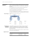
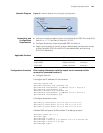
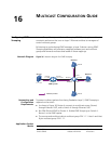
Network Diagram Figure 35 Network diagram for routing policy configuration
Networking and
Configuration
Requirements
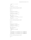
■ As shown in the figure above, Switch A and Switch B run OSPF. The router ID of
Switch A is 1.1.1.1 and that of Switch B is 2.2.2.2.
■ Configure three static routes and enable OSPF on Switch A.
■ Apply a routing policy on Switch A when redistributing the three static routes
so that the routes 20.0.0.0 and 40.0.0.0 are redistributed, and the route
30.0.0.0 is filtered out.
Applicable Products
Configuration Procedure Filter routing information with the import-route command and the
route-policy command (method 1)
■ Configure Switch A.
# Configure the IP addresses of the interfaces.
<SwitchA> system-view
[SwitchA] interface vlan-interface 100
[SwitchA-Vlan-interface100] ip address 10.0.0.1 255.0.0.0
[SwitchA-Vlan-interface100] quit
[SwitchA] interface vlan-interface 200
[SwitchA-Vlan-interface200] ip address 12.0.0.1 255.0.0.0
[SwitchA-Vlan-interface200] quit
# Configure three static routes.
[SwitchA] ip route-static 20.0.0.0 255.0.0.0 12.0.0.2
[SwitchA] ip route-static 30.0.0.0 255.0.0.0 12.0.0.2
[SwitchA] ip route-static 40.0.0.0 255.0.0.0 12.0.0.2
# Enable OSPF and specify VLAN-interface 10 to belong to area 0.
[SwitchA] router id 1.1.1.1
[SwitchA] ospf
[SwitchA-ospf-1] area 0
[SwitchA-ospf-1-area-0.0.0.0] network 10.0.0.0 0.255.255.255
[SwitchA-ospf-1-area-0.0.0.0] quit
[SwitchA-ospf-1]quit
Area 0
Vlan-Int 200
Router ID:
1.1.1.1
Switch A
Switch B
Router ID:
2.2.2.2
12.0.0.1/8
Static 20.0.0.0/8
30.0.0.0/8
40.0.0.0/8
10.0.0.1/8
10.0.0.2/8
Vlan-Int 100
Product series Software version Hardware version
Switch 5500 Release V03.02.04 All versions
Switch 5500G Release V03.02.04 All versions
Switch 4500 Release V03.03.00 All versions