


The Power-up Sequence 33
connection to an MDI port, you need to use a standard straight-through
cable. See Table 7.
WARNING: The 4400 PWR (3C17205) supports Power over Ethernet on
all front ports. These ports should only be used for Ethernet wiring within
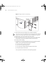
the same building. The Rear Module ports of the Switch 4400 PWR can
be used for ethernet wiring between buildings.
3Com recommends that you use Category 5 twisted pair cable — the
maximum segment length for this type of cable is 100 m (328 ft).
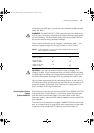
Table 7 Cables required to connect the Switch 4400 to other devices if
auto-negotiation is disabled
CAUTION: If you want to install the Switch using a Category 5E or
Category 6 cable, 3Com recommends that you briefly connect the cable
to a grounded port before connecting network equipment. If you do not,
the cable’s Electrostatic Discharge (ESD) may damage the Switch’s port.
You can create a grounded port by connecting all wires at one end of a
UTP cable to an earth ground point, and the other end to a female RJ-45
connector located, for example, on a Switch rack or patch panel. The
RJ-45 connector is now a grounded port.
Choosing the Correct
Cables
(Switch 4400 FX)
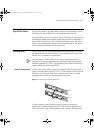
All of the ports on the front of the Switch 4400 FX are 100BASE-FX MT-RJ
multi-mode ports. The MT-RJ port is a small form factor fiber-optic port
with the transmit and receive fibers in the same cable. Unlike many
fiber-optic systems, only one MT-RJ cable is needed to connect two MT-RJ
ports together.
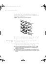
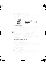
To connect a front-panel port to another 100BASE-FX MT-RJ multi-mode
port, or to a patch panel, a single MT-RJ multi-mode pinless jumper cable
is required. Since standard MT-RJ cables are cross-over cables, no
Cross-over Cable Straight-through Cable
Switch to Switch
(MDIX to MDIX)
✓
✕
Switch to Hub
(MDIX to MDIX)
✓ ✕
Switch to PC (NIC)
(MDIX to MDI)
✕
✓
DUA1720-3AAA07.book Page 33 Wednesday, March 17, 2004 1:14 PM