


24 C
HAPTER
2: I
NSTALLING
THE
S
WITCH
The Power-up
Sequence
The following sections describe how to get your Switch 610 powered-up
and ready for operation.
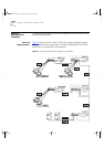
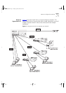
Connecting a
Redundant Power
System
You can connect a SuperStack II Advanced Redundant Power System
(part number 3C16071) to the Switch. This unit, which is also known as
an RPS, is designed to maintain the power to your Switch if a power
supply failure occurs.
CAUTION: The Switch can only use a SuperStack II Advanced
Redundant Power System output.
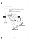
Powering-up the
Switch 610
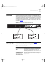
Use the following sequence of steps to power-up the Switch.
CAUTION: The Switch has no ON/OFF switch; the only method of
connecting or disconnecting main power is by connecting or
disconnecting the power cord.
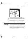
1
Plug the power cord into the power socket at the rear of the Switch.
2
Plug the other end of the power cord into your power outlet
The Switch powers-up and runs through its Power On Self Test (POST),
which takes approximately 12 seconds.
Checking for Correct
Operation
During the Power On Self Test, all ports on the Switch are disabled and
the Port Status LEDs light in a rapid cycle.
When the POST has completed, check the Power/Self Test LED to check
that your Switch is operating correctly. Ta bl e 4
shows possible colors for
the LED.
If there is evidence of a problem, see “Solving Problems Indicated by
LEDs” on page 25.
Table 4
LED colors
Color State
Green The Switch is powered-up and operating normally.
Yellow The Switch has failed its Power On Self Test. This
occurs if any of the ports fail during power-up.
Off The Switch is not receiving power.
16954ua.book Page 24 Friday, April 30, 1999 9:39 AM