


Connecting to a Network Device
Follow these guidelines to connect a device to the Baseline 8
Port Gigabit Switch:
Use Category 5 unshielded or shielded (screened) 100 Ohm
TP cable (or Category 3 cable for a 10 Mbps connection).
The maximum length of cable for each connection is
100 m (328 ft).
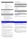
Connect one end of the cable to an RJ-45 port on the
Baseline 8 Port Gigabit Switch, and the other end to the
appropriate RJ-45 port on the connecting device.
Power Supply
Power problems can be the cause of serious failures and
downtime in your network. Ensure that the power input to your
system is clean and free from sags and surges to avoid
unforeseen network outages. 3Com recommends that you install
power conditioning, especially in areas prone to black outs,
power dips and electrical storms.
The unit is intended to be grounded. Ensure it is connected to
earth ground during normal use. Grounding the unit helps to
avoid damage from lightning and power surges.
Powering Up
Use the following sequence to power up the Baseline 8 Port
Gigabit Switch:
1 Check the network connections and cables.
2 Connect the power supply cable to the appropriate power
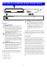
socket on the rear panel of the unit; see reference 5 in
“Features of the Baseline 8 Port Gigabit Switch.”
3 Connect the plug to the power supply outlet socket and
switch on the power supply at the socket.
When the switch is powered on, the Power LED lights green. If it
does not, see reference 4 in “Features of the Baseline 8 Port
Gigabit Switch.”
Introduction
The Baseline 8 Port Gigabit Switch is supplied with two
mounting brackets and four screws. These are used for rack
mounting the unit. When mounting the unit, you should take
note of the guidelines given in “Positioning the Switch” on
page 3.
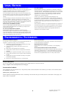
Rack Mounting the Units
The Baseline 8 Port Gigabit Switch is 1U high and will fit a
standard 19-inch rack.
CAUTION: Disconnect all cables from the unit before
continuing. Remove the self-adhesive pads from the
underside of the unit, if already fitted.
1 Place the unit the right way up on a hard, flat surface with
the front facing towards you.
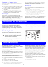
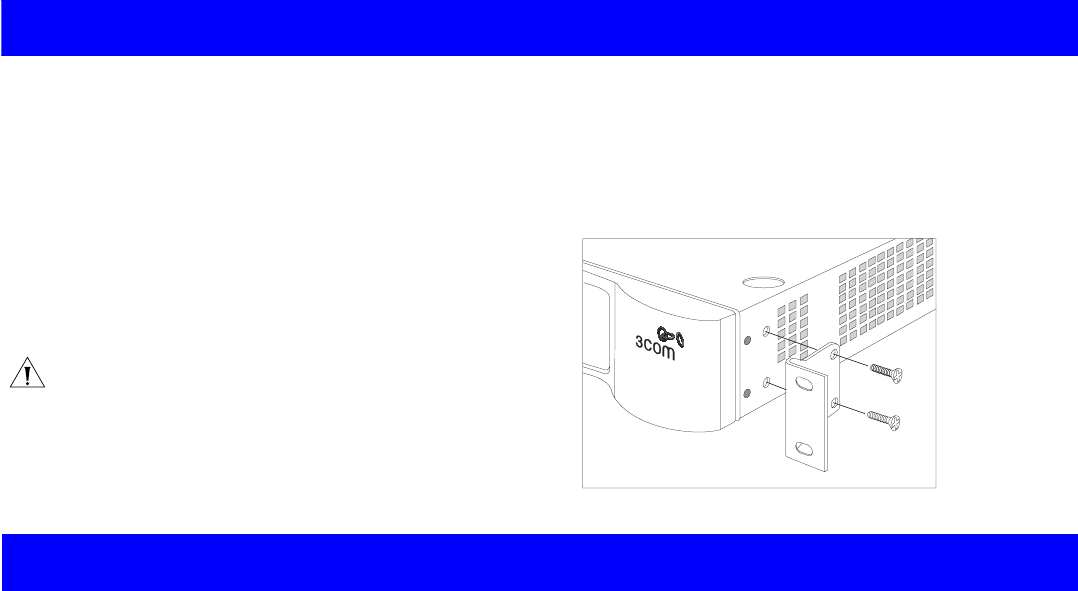
2 Locate a mounting bracket over the mounting holes on one
side of the unit (refer to the figure following step 6).
3 Insert the two screws supplied in the mounting kit and fully
tighten with a suitable screwdriver.
4 Repeat the two previous steps for the other side of the unit.
5 Insert the unit into the 19-inch rack and secure with suitable
screws (not provided).
6 Reconnect all cables.
At frequent intervals you should visually check the Baseline 8
Port Gigabit Switch. Regular checks can give you an early
warning of a possible failure; any problems can then be attended
to when there will be least effect on users.
Check that all external cabling connections are secure and that
no cables are pulled taut.
Refer to the information about LEDs given earlier in this guide to
see if the problem can be identified and rectified. Here are some
common problems that can occur:
Activity Status LED not lit for a port that has a connection.
There is a problem with this connection. Check that:
The device being connected to is powered on and operating
correctly.
The cable is connected at both ends.
You are using a TP cable that is not damaged.
If the connection is to a workstation, that the workstation’s
network interface is installed and configured correctly.
All Activity LEDs appear to be lit continually. There may be
broadcast storms on the network. Remove port connections one
at a time, waiting a few seconds between each port. If the LEDs
go off after removing a port connection, the device that was
connected to that port is introducing an excessive amount of
broadcast frames to the network (some pieces of network
equipment operate by sending out broadcast frames regularly).
Refer to the documentation that accompanies the device for
information on disabling the broadcast operation.
If the problem persists and the unit still does not operate
successfully, contact your supplier with the following information
before returning the unit:
Product number and serial number (printed on a label sup-
plied with the unit)
A brief description of the fault
MOUNTING KIT INSTRUCTIONS
PROBLEM SOLVING
4