


Installing the Module into a Switch
CAUTION: This Module is not hot-insertable or
hot-swappable. Always make sure that the Switch is
powered down and disconnected from the mains before
installing or removing a Module. Use the following
instructions when installing or removing a Module.
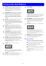
CAUTION: This Module is only designed to work with
the 3Com SuperStack 3 Switch 4900 series.
To install the Module:
1
Ensure that the Switch is disconnected from the mains
power supply and that you are wearing an anti-static
wristband connected to a suitable earth point.
2
Place the Switch on a flat surface. Using a suitable
screwdriver, remove the blanking plate from the rear of
the Switch. Do not remove any other screws from the
rear of the Switch.
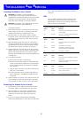
3
Keep the blanking plate and screws in a safe place. If
you remove the Module at any time, you must replace
the blanking plate to prevent dust and debris entering
the Switch and to aid the circulation of cooling air.
4
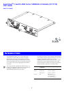
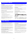
Hold the Module so that the text on the front panel is
upright, and insert it into the Switch, ensuring the back
panel is flush against the back of the Switch. Tighten
the three captive thumbscrews securing the Module with
a suitable tool.
5
To activate the Module:
a
Ensure that the Switch is powered-up.
b
Remove the protective stopper from the MT-RJ fiber
socket on the Module. Squeeze the top and bottom
of the stopper between your thumb and forefinger
then remove it.
c
Plug the MT-RJ connector on the fiber cable into the
fiber port on the Module.
d
Connect the other end of the fiber optic cable to a
device fitted with a 1000BASE-LX Gigabit Ethernet
connection.
6
Check the LEDs on the front of the Switch and the rear
of the Module to ensure that the Module is operating
correctly. Refer to “LEDs” below for more information.
Removing the Module from a Switch
1
Ensure that the power supply and the fiber backbone
connection cables are disconnected from the Switch.
2
Place the Switch on a flat surface. Undo the three
captive thumbscrews securing the Module into the
Switch. Do not remove any other screws from the
Switch.
3
If you are not fitting another Module immediately,
replace the blanking plate to ensure that dust and debris
do not enter the Switch and to aid the circulation of
cooling air.
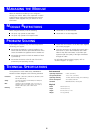
LEDs
You can gather information about the status of the
Module and its packet activity using the Expansion
Module LEDs on the front of the Switch and the Port
LEDs on the rear of the Module.
I
NSTALLATION
A
ND
R
EMOVAL
Expansion Module Activity LED (Switch)
Status Color Meaning
On Amber Packets are being transmitted or received
on the Module.
Off No color There are no packets being transmitted or
received on the Module.
Expansion Module Status LED (Switch)
Status Color Meaning
On Green N/A (cannot report status of all ports
together).
Off No color The Module is not installed.
Flashing Amber The Module is installed but is not
recognised (faulty or unsupported).
On Amber The Module is installed.
Port Activity LED (Module)
Status Color Meaning
On Amber Packets are being transmitted or received
on this port.
Off No color There are no packets being transmitted or
received on this port.
Port Status LED (Module)
Status Color Meaning
On Green A link is present and the port is enabled.
Off No color There is no link present.
Flashing Green A link is present and the port is disabled.
3