


1-2 CHAPTER 1: INTRODUCTION
General
Description
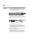
The front panel of the SuperStack II Hub 100 Management Unit, shown in
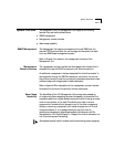
Figure 1-1, has a series of LEDs that supply status, unit, and environmental
information. A Reset button is located to the left of the LEDs. (Refer to
Chapter 2 for the interpretation of the LEDs.)
Figure 1-1 Front Panel of the SuperStack II Hub 100 Management Unit
Figure 1-2 shows the rear panel of the Management Unit. The two expansion
connectors are used for connecting the Management Unit to hubs to create a
hub stack.
Figure 1-2 Rear Panel of the SuperStack II Hub 100 Management Unit
The three-pronged socket lets you attach a 100–240 V AC power cord to
the unit. Alternatively, power can be supplied through a 3Com Redundant
Power System connected to the DC input connector. A 250 V, 2 A fuse is
located in the unit’s AC receptacle.
The console port is an RS-232 serial port that can connect to a local VT100
console or a modem-based remote console.
You can mount the Management Unit in a 19-inch standard rack with
SuperStack II Hub 100 repeater units. A rack-mounting kit is supplied with
each Management Unit. Refer to Chapter 2 for installation instructions.
UNIT
OVERTEMP
STATUS
FAULT
RESET
PWR
SuperStack II
Hub 100 Management
SUPER
STACK
Unit digital
display
Reset button
UP
DOWN
CONSOLE
EXPANSION
!
®
3Com Corporation
Santa Clara, CA
Made in USA
REFER TO
INSTRUCTION MANUAL
FOR CORRECT
SELECTION OF
POWER CORD
CAUTION: For continued
protection against risk of fire
use only with same type
and rating of anti-serge fuse.
INPUT
V
A max
5
5.0
+12
2.5
–12
0.2
DC INPUT
AC power cord socket
Fuse compartment
DC input
connector
Console
port
Expansion
connectors