


20
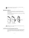
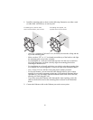
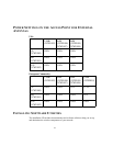
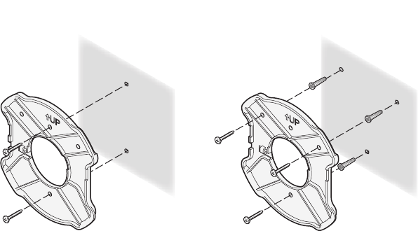
1 Install the mounting plate as shown in the following illustration, on either a stud
(or other hard wall surface), or onto drywall.
o Allow for a clearance of at least 25 cm (10 Inches) between the ceiling and the
top of the mounting plate.
o Make sure that “UP” or “A” is oriented toward the top of the bracket, and align
the mounting plate screw holes vertically.
o For installation on a wall stud, install the top screw into the stud, as shown at
left in the illustration, and then vertically align the mounting plate before
installing the bottom screw.
o For installation on to drywall, mark three screw holes using the mounting plate
as a template for vertical alignment, as shown at right in the illustration above.
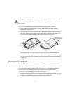
o Use a 5-mm (3/16-in.) drill bit if using the plastic anchors provided.
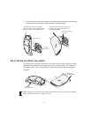
o For drywall mounts, you can route the cable through either a side or center
opening for a seamless appearance using one of the methods illustrated below.
Alternatively, you can simply attach the Ethernet cable to the side of the unit,
allowing it to trail along the wall.
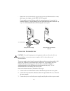
o If you have routed the Ethernet cable through the center opening, secure the
cable on the hook located on the mounting plate as shown in the illustration
below.
2 Connect the Ethernet cable to the Ethernet port on the access point.
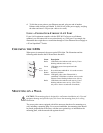
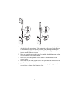
If installing into drywall, use
3 plastic anchors and 3 screws.
If installing into a stud or other
secure vertical surface, use 2 screws.