17
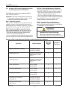
The crate should also contain the following:
• One warning beacon with bracket (electrically
connected, but not mounted in place)
7.4 Machine Positioning / Bed Height
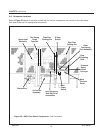
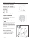
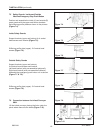
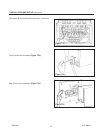
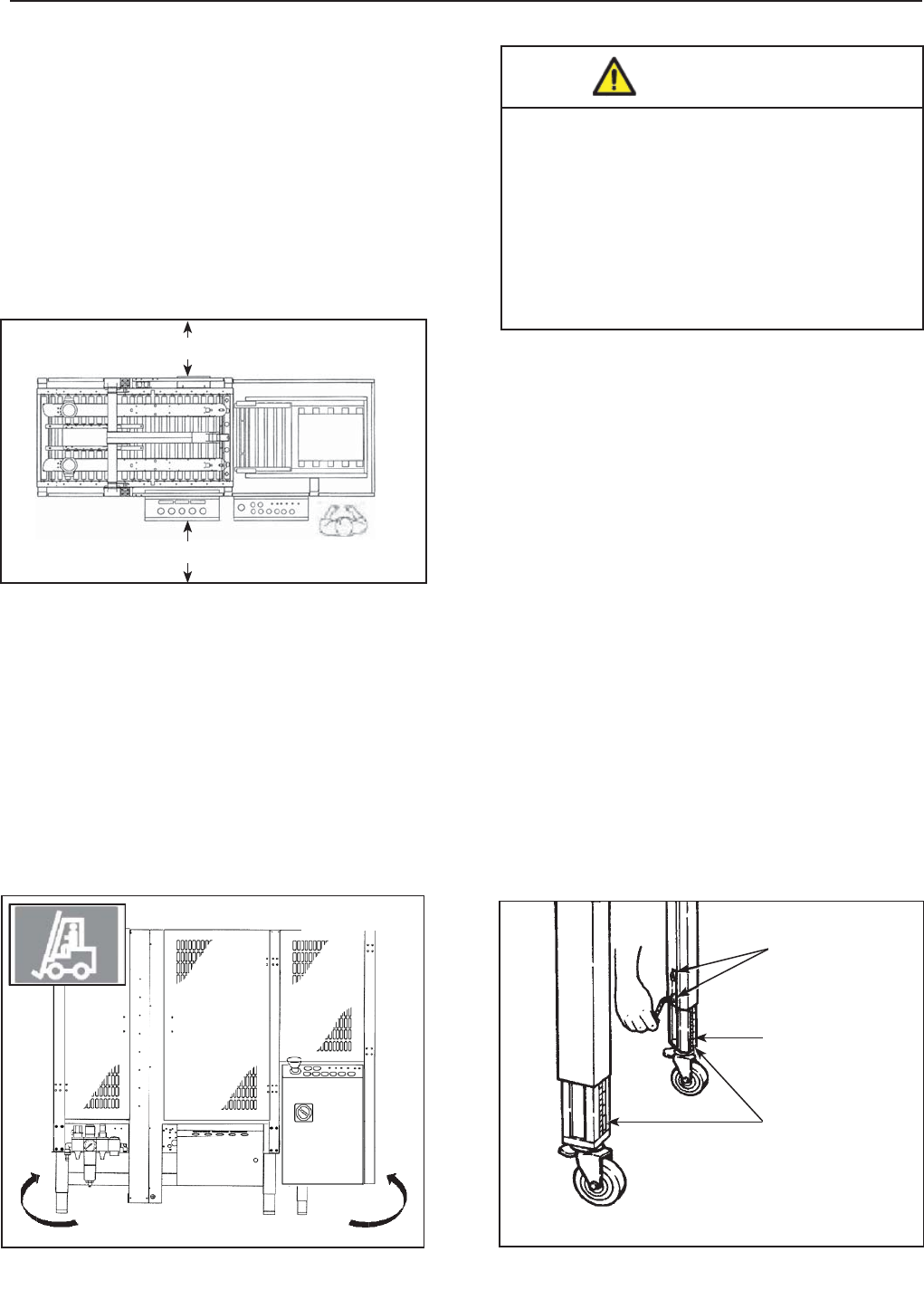
Lift the machine with belts or ropes paying attention
to place the belts in the points (Figure 7-2).
To set the machine bed height, do the following:
7-INSTALLATION
2012 March
800rf-NA
The legs on the case sealer can be adjusted to obtain
different bed heights from the factory set-point. The
bed height can be set from 25-7/8 inches [657mm]
minimum through 32 inches [815mm] maximum. Set
the bed height as follows:
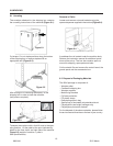
1. Block up the case sealer frame to allow adequate
leg adjustment.
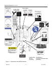
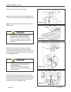
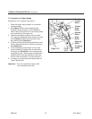
2. Using a 6mm hex key wrench, loosen, but do not
remove, two (2) M8 x 16mm socket-head cap
screws in one leg. Refer to Figure 7-3.
3. Using the height label as a guide, adjust the leg
length to the desired conveyor bed height. Re-
tighten the two (2) screws to secure the leg.
4. Adjust the remaining legs in the same way.
Figure 7-3
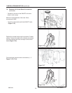
A tool kit containing some tools are supplied with
the machine. These tools should be adequate to
set-up the machine, however, other tools supplied
by the customer will be required for machine
maintenance.
7.3 Tool Kit / Parts Supplied with the Machine
7.1 Operating Conditions
The machine should operate in a dry and relatively
clean environment (See Specifi cations).
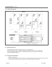
7.2 Space Requirements for Machine Operation
and Maintenance Work
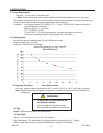
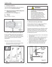
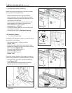
Minimum distance from wall (Figure 7-1):
A = 1000mm.
B = 700mm.
Minimum height = 2700mm.
• To reduce the risk associated with
muscle strain:
− Use the appropriate rigging and
material handling equipment when
lifting or repositioning this equipment.
− Use proper body mechanics when
removing or installing taping heads
that are moderately heavy or may be
considered awkward to lift.
WARNING
Forklift on Opposite Side
Figure 7-2
Figure 7-1
M8 x 16mm
Socket Head
Screws
Adjustable
Legs
Height
Label
A
B


