


6
The knife change must be executed by one person only. The cutting edge of the knife is extremely
sharp. In order to avoid injuries, the knife has to be handled with the utmost care. Transportation
of knife is only permitted in specially designed wooden cases, which are supplied with every spare
knife ordered from your local distributor.
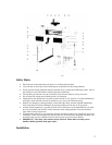
The following description applies to model IDEAL 4810-11. Please note, that with models
IDEAL 4810 and IDEAL 5210 the re-set button (#12) must be pushed prior to activating the knife
with the two push buttons (#5).
1. Turn the cutting depth adjustment screw (#4) all the way to the left (-) and then a complete
turn to the right (+).
2. Bring the knife down by pressing both push button switches (#5). Release one of the switches
and turn main switch (#11) to position “0” (off). The knife stays in its lowest position on the
cutting stick (#2).
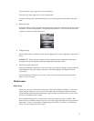
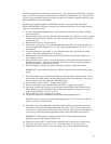
3. Remove knife screw (E). See illustration I.
4. Remove the securing screw (F) on the knife adjustment flap (#20). Lift up the flap (#20) and
turn out the three knife adjustment screws (X, Y, and Z) by approximately 5 mm (1 /4”). See
illustration II.
5. Turn main switch (#11) to position “|” (on). The knife carrier (#17) goes back to its home
position. Turn main switch back to “off” position.
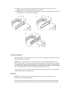
6. Remove knife screws (B and D) and replace them with the two knife holders from the tool
box. Tighten securely.
7. Take out knife screws (A and C), loosen knife holders and lower the knife downwards from
the knife carrier (#17). Then, due to the length of the knife, a sideways movement between
the knife guide plates is required for removal.
8. Take out cutting stick (#2), turn, rotate or exchange it and place it back into machine.
IMPORTANT – Hook cutting stick into pin, which is located on left between the knife guide
plates.
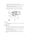
9. Insert knife holders into second and fourth threaded hole (B and D) of the new knife. Ensure
that the ends of the knife holders are protruding from the other side of the knife. Place knife
(#18) into knife carrier (#17) and secure with knife holders.
10. Screw in knife screws (A and C) – snuggly, don’t tighten.
11. Remove knife holders. Screw in knife screws (B and D) – snuggly, don’t tighten.
12. Spread one to three sheets of paper across the entire cutting length. Bring the knife (#17)
down. Release only one push button (#5) and turn main switch (#11) to position “0” (off)
again to stop the knife in its lowest position.
13. Screw in knife screw (E) – snuggly, don’t tighten.
14. The parallel adjustment of the knife is done via the knife adjustment screws.
Push knife down by screwing in the knife adjustment screws (X, Y, and Z) evenly, until the
paper is cut across its whole length.
15. Should the scope of the adjustment available by means of the knife adjustment screws be
insufficient, resort to the knife depth adjustment screw (#4). Turn it in steps of half a turn
clockwise (+). After each step a test cut has to be executed. If the paper is cut through only
on one side, proceed with parallel adjustment of knife as described under (#12 and #14).
IMPORTANT – Both the above methods (#14 and #15) of knife adjustment offer an
adjustment range of approximately 5 mm (1 / 4”).
16. Tighten knife screws (B, C, D and E) firmly while the knife is lowered on the cutting stick.
17. Turn main switch (#11) to position “|” (on). The knife returns to its home position.
18. Tighten knife screw (A) firmly. Screw in securing screw for knife adjustment flap (#20).