


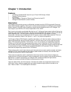

Chapter 6: Connector Pin Assignments
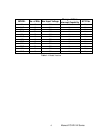
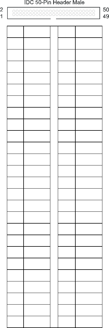
Isolated inputs are connected to the card via a 50-pin HEADER type connector. There are three
connectors named PORT0, PORT1, and PORT2. The table below describes PORT0. PORT1 and
PORT2 are identical pinouts. Pin 50 is located toward the Jumpers, while Pin 1 is located near connection
to Motherboard.
PIN NAME
PIN NAME
1 GND
2 NC
3 Bit 0 A
4 Bit 0 B
5 NC
6 Bit 1 A
7 Bit 1 B
8 NC
9 Bit 2 A
10 Bit 2 B
11 NC
12 Bit 3 A
13 Bit 3 B
14 NC
15 Bit 4 A
16 Bit 4 B
17 NC
18 Bit 5 A
19 Bit 5 B
20 NC
21 Bit 6 A
22 Bit 6 B
23 NC
24 Bit 7 A
25 Bit 7 B
26 NC
27 Bit 8 A
28 Bit 8 B
29 NC
30 Bit 9 A
31 Bit 9 B
32 NC
33 Bit 10 A
34 Bit 10 B
35 NC
36 Bit 11 A
37 Bit 11 B
38 NC
39 Bit 12 A
40 Bit 12 B
41 NC
42 Bit 13 A
43 Bit 13 B
44 NC
45 Bit 14 A
46 Bit 14 B
47 NC
48 Bit 15 A
49 Bit 15 B
50 NC
Manual PCI-IDI-XX Series 15