


Quick Installation GuideCheetaHub Power-3008N/3016N
2 3
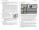
Note: If more than one hub with internal switching is used in the stack, switching
between stack segments will be managed by the unit highest in the stack, and
internal switching will be disabled for all other units.
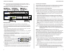
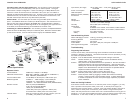
These hubs provide a friendly design that simplifies installation and network
troubleshooting. The following figure shows the components of these hubs:
Mounting the Hub
These hubs can be placed directly on your desktop or on any flat surface.
Before you start installing the hub, make sure you can provide the right operating
environment, including power requirements, sufficient physical space, and proximity
to other network devices that are to be connected. Verify the following installation
requirements:
Power requirements: 100 to 240 VAC (± 10%) at 50 to 60 Hz (± 3Hz). The hub's
power supply automatically adjusts to the input voltage level.
The hub should be located in a cool dry place, with at least 10 cm. (4 in.) of space
at the front and back for ventilation.
Place the hub out of direct sunlight, and away from heat sources or areas with a
high amount of electromagnetic interference.
Check if network cables and connectors needed for installation are available.
Stacking Hubs on a Flat Surface
These CheetaHubs can be stacked anywhere there is a enough flat space, such as
on a table or desktop.
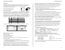
1. Stick the self-adhesive rubber foot pads
(that come with this package) on each
of the 4 concave spaces located on the
bottom of the first hub.
2. Place the first hub on a firm flat surface where you want to install the stack.
3. Repeat step 1 for each hub before stacking them. The rubber foot pads cushion
the hub against shock/vibrations and provide space between each hub for
ventilation.
4. For added stability when stacking hubs, you can purchase the optional Stack Mount
Brackets from your Accton distributor, and secure each hub to the adjacent unit.
Connecting the Hub System
These hubs have 8 (or 16) RJ-45 dual-speed RJ-45 station ports, one of which also
serves as a dual-speed MDI daisy-chain port. Two stack backplane ports are also
located on the rear panel; using these ports you can stack up to six hubs.
Making a Connection via an RJ-45 Station Port
You can connect any RJ-45 (MDI-X) station port on the hub to any device that uses
a standard network interface such as a workstation or server, or to a network inter-
connection device such as a bridge or router (depending on the port type implemented).
1. Prepare the network devices you wish to network. Make sure you have installed
10BASE-T or 100BASE-TX network interface cards for connecting to the hub's
RJ-45 (MDI-X) station ports.
2. You also need to prepare straight-through shielded or unshielded twisted-pair
cables with RJ-45 plugs at both ends. Use 100Ω Category 3, 4 or 5 cable for
standard 10 Mbps Ethernet connections, or 100Ω Category 5 cable for 100 Mbps
Fast Ethernet connections.
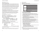
3. Connect one end of the cable to the RJ-45 port of the network interface card, and
the other end to any available (MDI-X) station port on the hub. The RJ-45 ports
support 10 Mbps and 100 Mbps Ethernet connections. When inserting an RJ-45
plug, be sure the tab on the plug clicks into position to ensure that it is properly
seated. Using a hub in a stand-alone configuration, you can network up to 8 (16)
end nodes.
I Do not plug a phone jack connector into any RJ-45 port. This may damage the hub.
Use only twisted-pair cables with RJ-45 connectors that conform with FCC standards.
Notes: 1. Make sure each twisted-pair cable does not exceed 100 meters (328 feet).
2. We advise using Category 5 cable for all network connections to avoid any
confusion or inconvenience in the future when you upgrade attached devices
to Fast Ethernet.
Making a Connection to the BNC Port (EH3016N, EH3016N-SW only)
Plug the BNC T-type connector (provided with the hub) into a BNC port on the back
of the EN3016N or EN3016N-SW. When connecting two devices via BNC ports,
there should be at least 0.5 meters (1.64 feet) of coaxial cable between the two BNC
ports. A thin Ethernet coaxial cable segment can be extended up to 185 meters
(607 feet) and can link up to 30 nodes. If the unit is at the terminal end of a
segment, connect a 50Ω terminator to the open end of the "T" connector.
Making a Connection via an MDI Daisy-Chain Port
Use the RJ-45 MDI daisy-chain por to connect to another compatible hub or switch.
1. Prepare straight-through shielded or unshielded twisted-pair cables with RJ-45
plugs at both ends. Use 100Ω Category 3, 4 or 5 cable for standard 10 Mbps
Ethernet connections, or 100Ω Category 5 cable for 100 Mbps Fast Ethernet
connections.
2. Connect the MDI port on the switch to any MDI-X station port on the other device.
When inserting an RJ-45 plug, be sure the tab on the plug clicks into position to
ensure that it is properly seated.
Notes: 1. Make sure each twisted-pair cable does not exceed 100 meters (328 feet).
2. To connect to another hub or switch, you can also connect from any MDI-X
port on the switch to an MDI daisy-chain port on the other device, or attach to
(MDI-X) station ports at both ends using crossover cable.