


Chapter 3 58
Disassembly Procedure Flowchart
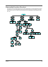
The flowchart on the succeeding page gives you a graphic representation on the entire disassembly sequence
and instructs you on the components that need to be removed during servicing. For example, if you want to
remove the main board, you must first remove the keyboard, then disassemble the inside assembly frame in
that order.
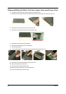
HDD cover
Start
L&R hinge
cover
Memory cover
miniPCI
cover
HDD module
HDD
assembly
HDD
bracket
DDR2
DDR1
miniPCI board
Keyboard
LCD&Upper
case
Lower case
assembly
Speaker
cable
USB
module
ODD
module
Power
board
Touchpad
bracket
Touchpad
board
LCD
module
Upper
case
Lower case
assembly
Mainboard
LCD bezel
Speaker
set
Audio
board
MDC
module
Thermal
module
CPU
Cardbus
MDC
board
MDC
cable
LCD
inverter
LCD
cover
LCD
assembly
Antenna
set
LCD
bar
LCD
bracket
LCD
coaxial
cable
x2
Dx2
Dx2
Ex19,Dx3,Ex5,Gx2
x2
x2
Dx2
Dx4
Dx7
x3
Dx2
Dx2
x1
Dx4
Fx2
Ex4,Dx2
Ax4
Bx8
Ax4