


19
15
6
10
11 15
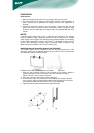
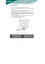
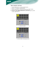
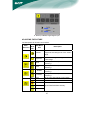
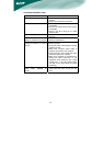
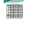
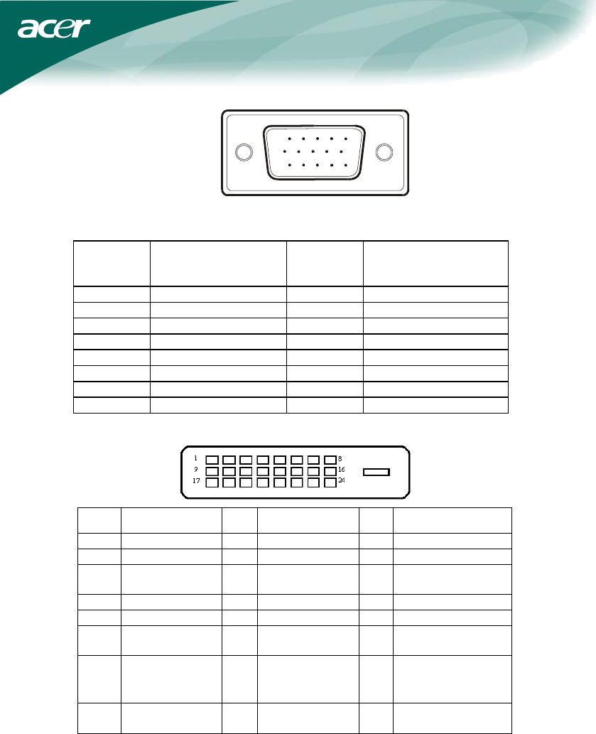
15 - Pin Color Display Signal Cable
PIN NO.
DESCRIPTION
PIN NO.
DESCRIPTION
1. Red 9. +5V
2. Green 10. Logic Ground
3. Blue 11. Monitor Ground
4. Monitor Ground 12. DDC-Serial Data
5. DDC-return 13. H-Sync
6. R-Ground 14. V-Sync
7. G-Ground 15. DDC-Serial Clock
8. B-Ground
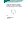
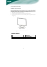
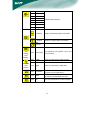
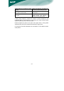
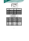
(Dual-Input Model)
Pin Meaning Pin Meaning Pin Meaning
1. TMDS Data2- 9. TMDS Data1- 17. TMDS Data0-
2. TMDS Data2+ 10. TMDS Data1+ 18. TMDS Data0+
3.
TMDS Data
2/4 Shield
11.
TMDS Data
1/3 Shield
19.
TMDS Data 0/5
Shield
4. TMDS Data4- 12. TMDS Data3- 20. TMDS Data5-
5. TMDS Data4+ 13. TMDS Data3+ 21. TMDS Data5+
6. DDC Clock 14. +5V Power 22.
TMDS Clock
Shield
7. DDC Data 15.
GND(return for
+5V
hsync.vsync)
23. TMDS Clock+
8.
Analogue
Vertical Sync
16.
Hot Plug
Detect
24.
DDC TMDS
Clock-
CONNECTOR PIN ASSIGNMENT