


4
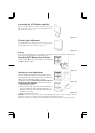
Connecting the LCD Monitor and Base
When you open the box to take the base and put on
the desk first. Then connect the LCD Monitor and
base please.(See fig.1-1 )
Figure 1-1
Viewing Angle Adjustment
The LCD Monitor is d
esigned to allow users to have
a comfortable viewing angle. The viewing angle can
be adjusted from -5°to +30°.(See fig. 1-2)
Figure 1-2
Warning
Do not force the LCD Monitor over its maximum viewing angle settings as stated above. Attempting this
will result in damaging the Monitor and Monitor stand.
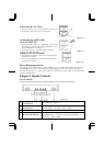
Detaching LCD Monitor from Its Stand
Unscrew screws Πthe swivel base support column
and pull
down• the hinge to release.
Figure 1-3
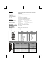
Interface for Arm Applications
Before installing to mounting device, please refer to Fig.1-3.
The rear of this LCD display has four integrated 4 mm, 0.7
pitches threaded nuts, as well as four 5 mm access holes in the
plastic covering as illustrated in Figure 1-4. These
specifications meet the VESA Flat Panel Monitor Physical
Mounting Interface Standard
(paragraphs 2.1 and 2.1.3,
Figure 1-4
Connecting the Display
1. Power off your computer.
2. Connect one end of the signal cable to the LCD Monitor’s
VGA port or DVI port.(For AL712/AL713)(See Fig 1-5)
3. Connect the other end of the signal cable to the VGA port
or DVI port on your PC.
4.
Make sure connection are secure
.
Figure 1-5
Attention: This device must be connected to an off-the-shelf video cable in order to comply with FCC
regulations. A ferrite-core interface cable is included in the LCD Monitor package.
This device will not be in compliance with FCC regulations when a non-ferrite-core video cable is used.