


7
Chapter 1 Monitor Features ----------------------------------------------------------------- 6
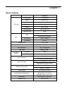
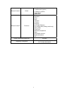
Monitor Features --------------------------------------------------------------------------- 8
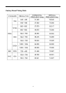
Factory Preset Timing Table -----------------------------------------------------------10
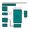
Block Diagram ------------------------------------------------------------------------------11
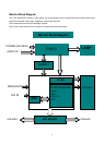
Main board Diagram ----------------------------------------------------------------------12
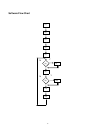
Software Flowchart ----------------------------------------------------------------------- 13
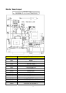
Main board Layout ------------------------------------------------------------------------ 15
Inverter Board Layout ---------------------------------------------------------------------17
Front Bezel ---------------------------------------------------------------------------- ------18
Rear Bezel -----------------------------------------------------------------------------------19
Chapter 2 Operating Instructions ----------------------------------------------------------- 20
External Controls ----------------------------------------------------------------------------20
Front Panel Controls -----------------------------------------------------------------------20
OSD Menu ------------------------------------------------------------------------------------22
Hot-Key Menu --------------------------------------------------------------------------------25
OSD Message --------------------------------------------------------------------------------26
LOGO -------------------------------------------------------------------------------------------27
Chapter 3 Machine Disassembly --------------------------------------------------------------28
Chapter 4 Troubleshooting --------------------------------------------------------------------- 31
Chapter 5 Connector Information ------------------------------------------------------------ 34
Chapter 6 FRU (Field Replacement Unit) List -------------------------------------------- 35
Exploded Diagram ---------------------------------------------------------------------------35
Chapter 7 Schematic Diagram ---------------------------------------------------------------- 40
Analog Input --------------------------------------------------------------------------------- 40
Input -------------------------------------------------------------------------------------------- 41
Scaler TSU16AK ---------------------------------------------------------------------------- 42
Panel Interface ------------------------------------------------------------------------------- 43
MCU -------------------------------------------------------------------------------------------- 44
Appendix Online Support Information ------------------------------------------------------ 45
Table of Contents