


PC 2120 All-in-One 12.1” TFT LCD Panel PC User’s Manual
C h a p t e r 3
Hardware Installation
This chapter describes the installation and the cable connection to the
system connectors. See system board User’s Manual that came with
your PANEL PC packaging for more details. Sections in this chapter
includes:
z
CPU
z
DRAM
z
HDD
z
3 x Serial Ports
z
Parallel Port
z
VGA
z
Ethernet
z
Keyboard
z
PS/2 Mouse
z
Cash Drawer(610e only)
z
Dallas Key(option)
z
Expansion Slot
z
System O/S and Software Installation
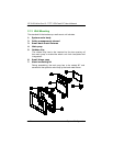
The PC 2120 series has either a Pentium or a Pentium III/Celeron little
board with a free PCI slot inside and a 3.5” HDD drive bay. These
come as standard configuration of the system. Upgrading to a higher
performance CPU, higher capacity DRAM modules and hard disk
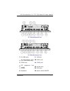
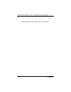
drive can increase system performance. The user can use the I/O
ports located at the bottom layer of the chassis to connect external
peripheral devices, such as a monitor, serial devices, parallel
printer…etc.
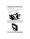
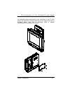
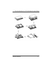
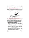
If you encounter difficulties during connection, loosen the screws on
the cable management shroud, then remove the shroud for easy
peripheral connection.
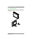
NOTE:
Make sure th
e power cor
d is disconnected before any
ins
t
alla
tion. To
ins
t
all a
ny in
t
e
rnal device s
uch as
CPU, DRAM
and HDD,
take out the p
l
astic rear cover and unscrew the
metal rear bracket first.
Hardware Installation
15