


Chapter 3 49
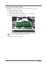
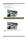
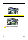
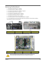
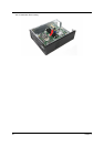
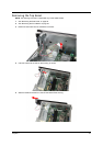
Removing the Mainboard
1. See “Removing the Side Panel” on page 29.
2. See “Removing the Front Bezel” on page 30.
3. See “Removing the Heatsink Fan Assembly” on page 32.
4. See “Removing the Processor” on page 34.
5. See “Remove the HDD-ODD bracket” on page 36.
6. See “Removing the Memory Modules” on page 42.
7. See “Removing an Expansion Card” on page 43.
8. See “Removing the Front I/O and Card Reader Boards” on page 46.
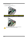
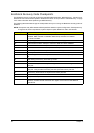
9. For the X5950 model, disconnect the LED cable from its mainboard connector before proceeding.
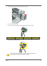
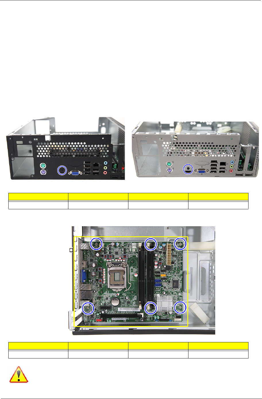
10. Remove the screw (C) on the rear panel.
11. Remove the six screws (B) that secure the mainboard to the housing.
Screw (Quantity) Color Torque Part No.
M3xL5 BZN (1) Black 5.5 to 6.5 kgf-cm 86.1A324.5R0
Screw (Quantity) Color Torque Part No.
#6-32 L6 NI (6) Silver 5.7 to 6.3 kgf-cm 86.00J44.C60
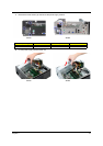
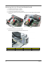
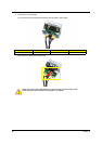
NOTE: The mainboard has been highlighted with a yellow rectangle as above image
shows. Please detach the mainboard and follow local regulations for disposal.
X3950 X5950