3-30 Machine Maintenance Procedures
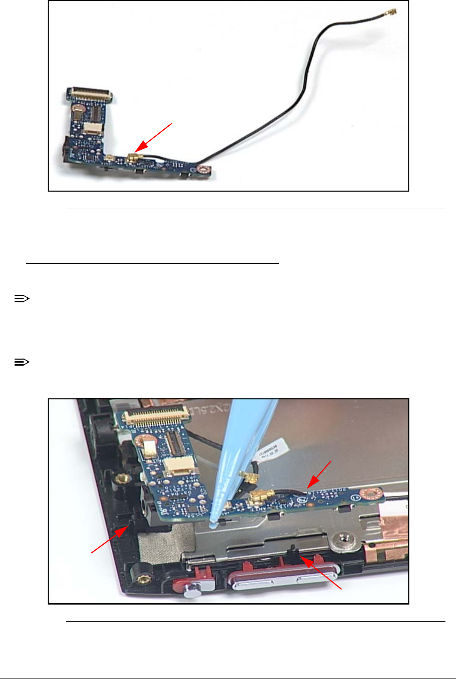
7. Disconnect RF cable from IO board connector (H).
Figure 3-40. IO Board and RF Cable
IO Board Installation 0
1. Connect RF cable (H) to IO board connector. (Figure 3-40)
NOTE:
NOTE:
Light sensor must be secured in support plate guide.
Microphone cable must be under IO board.
2. Align IO board with bezel guides (J). (Figure 3-41)
NOTE:
NOTE:
RF cable must be secured under IO board guides (K).
Figure 3-41. IO Board and Bezel Guides
3. Install board on bezel.
H
J
J
K


