ADCP-92-063 • Issue 1 • May 2005
Page 10
© 2005, ADC Telecommunications, Inc.
4 SPECIFICATIONS
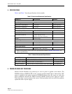
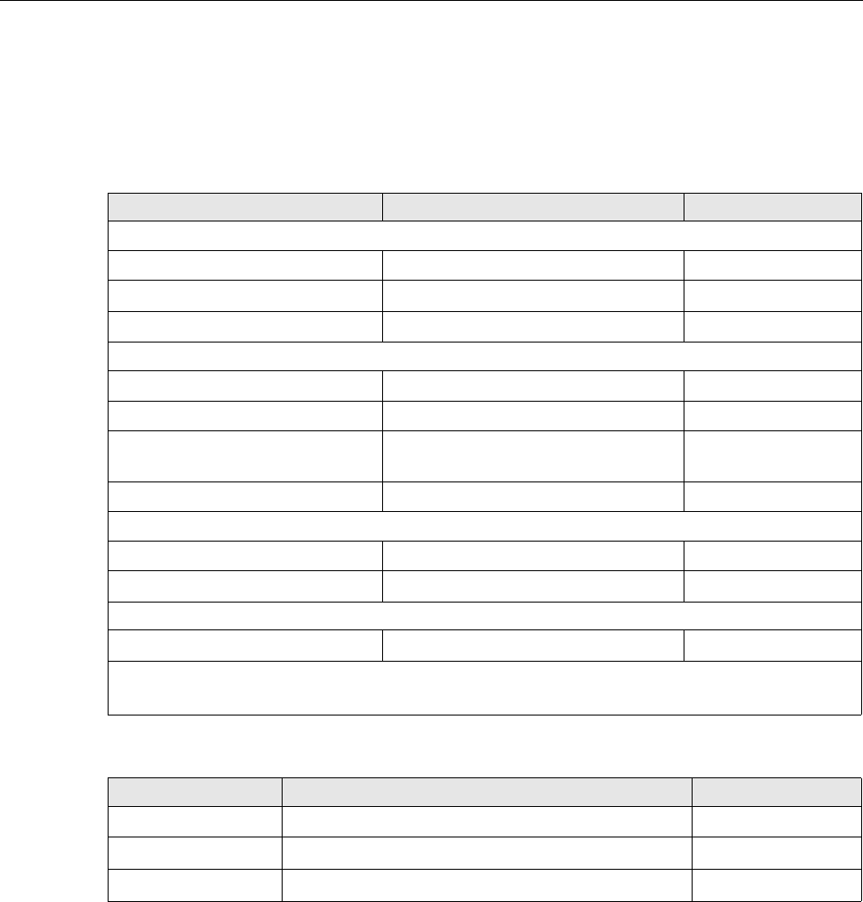
Table 6 and Table 7 lists the specifications for the module.
5 POWER-UP/CHECK OUT PROCEDURE
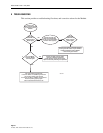
Media Converter Modules are powered up as soon as power is applied to the chassis. The
POWER indicator (GREEN LED) on the converter module should light to indicate that VDC
power is applied to the media converter. If POWER indicator does not come on, verify that
power connections between the Media Converter Module and the power supply are secure.
Verify that there is power present at the source. If this procedure does not resolve the problem,
replace the cable or power supply.
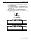
Table 6. Electrical and Mechanical Specifications
PARAMETER SPECIFICATION REMARKS
Electrical
Input Voltage +5 VDC Backplane connector
Input power (10/100 Mb/s) 1.75 W max. Normal operation
Input power (1000 Mb/s) 2.2 W max. Normal operation
Mechanical
Chassis Compatibility OptEnet Media Converter All modular systems
Module Retention Captive thumbscrews
Dimensions
(H
×
W
×
D) 1.14 in.
×
8.07 in.
×
7.4 in.
(2.89 cm
×
20.5 cm
×
18.8 cm)
Weight 0.27 lb. (122 g.)
Electrical Signal Interface
RJ45 Two twisted pair 10/100 Mb/s
RJ45 Four twisted pair 1000 Mb/s
Optical Signal Interface
LC Singlemode 1410 – 1610 nm *
* -
Refer to the OptEnet SFP Transceiver Specifications listed in Related Publications, for
optical specifications.
Table 7. Module Environmental Specifications
PARAMETER SPECIFICATION REMARKS
Operating Conditions 41°F to +104°F (5°C to +40°C) Per Telcordia GR-63
Short Term Conditions
+23°F to +122°F (−5°C to +50°C)
Per Telcordia GR-63
Storage Conditions
−40°F to +185°F (−40°C to +85°C) at 5% to 95% RH
Non-condensing


