


5/08 • 104974AE
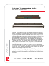
ProPatch
®
Programmable Series
ProPatch
®
Programmable Series
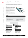
High-Density Patching Systems
3
www.adc.com • +1-952-938-8080 • 1-800-366-3891
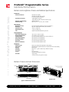
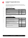
Bantam and Longframe Chassis and Module Specifications
ELECTRICAL
Contact resistance: 0.020 W max (initial)
0.020 W max (after life cycling)
0.10 W max (after salt spray)
Insulation resistance: 10,000 MW min (initial)
1,000 MW min (after moisture resistance test)
Dielectric withstanding: Voltage: 500 Vac
Contact rating: Max: 100 mA + 130 Vdc; Min: -40 dBm
MECHANICAL
Mechanical shock: Per MIL-STD-202F, Method 213B, test condition H
Vibration: MIL-STD-1344, Method 2005, test condition I
Insertion force: 7 lbs (3.17 kg) max
Withdrawal force: 1.5 lbs (.679 kg) min
Life: 20,000 insertion/withdrawal cycles min
ENVIRONMENTAL
Operating temperature: -40° to 65°C (-40° to 149°F)
Storage temperature: -55° to 85°C (-67° to 185°F)
Thermal shock: Per MIL-STD-202F, Method 107G, test condition A
Operating humidity: 0% to 95% (no condensation)
Storage humidity: 0% to 95% (no condensation)
Salt spray: Per MIL-STD-202F, Method 101D
Moisture resistance: Per MIL-STD-202F, Method 106E
MATERIALS
Chassis frame: Steel, zinc plated with electroless nickel plating
Jack frame: Unreinforced polyetherimide resin rated UL 94-V0 for flammability
Springs: Nickel-silver
Contacts: WECO No. 1 gold crossbar alloy welded to springs
PC boards: FR-4
Sockets: Phosper bronze
30 micro inches gold on contact
Switches: Copper alloy
10 micro inches min gold on contact
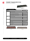
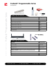
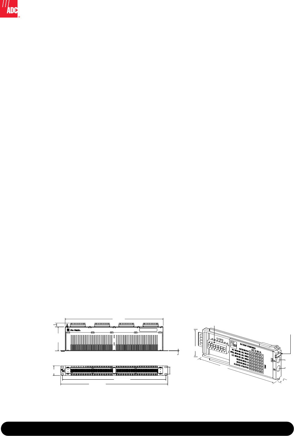
442 mm
(17.4")
108 mm
(4.25")
17.1 mm
(.673")
31.8 mm
(1.25")
2.3 mm
(.09")
465.3 mm
(18.32")
482.6 mm
(19")
43.7 mm
(1.72")
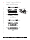
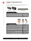
Programming Switch Circuit status icon identier
with 3 colors included
(8 colors available)
84 mm
(3.3”)
8 mm
(.312”)
30 mm
(1.2”)
7.5 mm
(.295”)
Bantam Jack
(top view)
(front view)
Bantam Chassis and Jack Dimensions
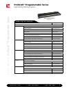
Typical 1 RU 48-Position Panel