


www.addonics.com Technical Support (M-F 8:30am - 6:00pm PST) Phone: 408-453-6212 Email: www.addonics.com/support/query/
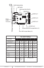
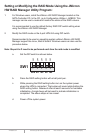
Note: When the default factory RAID setting is used, independent drive configuration
and optical drive are supported only when connecting to controllers with Silicon
Image Sil3124, Sil3132 chip set or controllers that are Port Multiplier (PM)
compatible. Simultaneous DVD writing was tested using the Nero Burning Rom.
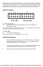
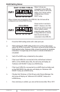
LED Pin Header
J1 – Drive Activity LED
P5 – Activity LED for eSATA host port lights up when it is connected to a
SATA controller card.
P0, P1, P2, P3 & P4 - Activity LEDs for port 0, 1, 2, 3, 4 & 5 light up when a drive is
connected and blinks when there’s drive activity.
J3 – Error LED
P5 – error LED for eSATA host port
P0, P1, P2, P3 & P4 - error LED for port 0, 1, 2, 3, 4 & 5
Cable Connections
1. Attach the SATA hard drives (up to 5) to the SATA ports on the Hardware
Port Multiplier (HPM) using SATA cables. It is recommended to connect
drives to the SATA ports 1 to 5 successively.
2. To provide power to the HPM, connect a 4-pin floppy power cable from the
system power supply to the floppy power connector on the HPM.
3. Optional: Connect LEDs to the Activity & Error LED jumper block
J3 J1
Error LED Activity LED
P4 P3 P2 P1 P0 P5 P4 P3 P2 P1 P0 P5