


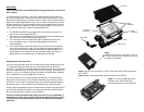

Step 5 Mount the board to the bottom
cover.
Step 6 Put the top cover on by holding it in
near vertical position and sliding the two
metal clips inside the two small slots on the
rear of the bottom cover.
Step 7 Lower the front of the top cover and making sure the two covers lined up
properly. Tighten the small retaining screw on the front of the bottom cover to
close the enclosure.
Cable Connections
Model: RCMR256I
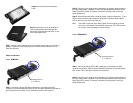
Step 1: Connect the 40-pin IDE ribbon cable that is connected to the IDE
controller on the motherboard to the 40-pin IDE connector attached at the back of
the Ruby Cipher drive cradle. This is the data connection for the device.
Step 2: Connect a 4-pin floppy power cable from your system’s power supply to
the 4-pin floppy power connector on the IDE bridge attached at the back of the
Ruby Cipher drive cradle. This power connection provides power to the ruby
cipher mobile rack.
Step 3: Slide the Ruby enclosure inside the cradle. Insert the Cipher key. To turn
ON the drive enclosure, place switch on INT position. Observe that the green
LED on the front of the enclosure lights up.
Note: If the LED on the front of the Ruby Cipher enclosure lights up as red
color, turn of the system and reseat the cipher key. The LED must turn
on as green color indicating it is setup correctly.
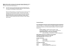
Model: RCMR256SC
Step 1: Connect the 68-pin SCSI ribbon cable that is connected to a SCSI
controller to the 68-pin SCSI connector attached at the back of the Ruby Cipher
drive cradle. This is the data connection for the device.
Step 2: Connect a 4-pin floppy power cable from your system’s power supply to
the 4-pin floppy power connector on the SCSI bridge attached at the back of the
Ruby Cipher drive cradle. This power connection provides power to the ruby
cipher mobile rack.
Mounting holes for
3 ½” drive bay
Mounting holes for
3 ½” drive bay