


2. Installation Wiring the ADT-APS-6R
12
ADT-APS-6R Instruction PN 50935:B 7/21/00
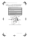
Wiring the ADT-APS-6R
This section contains instructions for wiring the Auxiliary Power Supply
as follows:
• Typical field wiring from an ADT-APS-6R to a control panel and
optional devices.
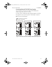
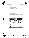
• Wiring multiple ADT-APS-6R power supplies.
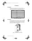
Field Wiring an ADT-APS-6R
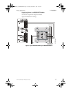
You can use J1 and J2 in place of TB2 when the ADT-APS-6R is
powering internal modules (such as an ICM-4, ICE-4, ADT-UZC-256,
XPC-8) with compatible connectors.
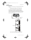
Output Circuit 3 (J9) can be used as a source of power for the XPIQ Audio
Transponder only.
Note: When using the J9 connector do not use the J2 connector. This will satisfy the
0.25 (6.35mm) requirement for separation between power-limited and nonpower-
limited circuits.
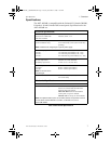
Primary and Secondary Power Connections - See appendix for your
specific system information.
Caution: When finished wiring AC connections, install the press-fit
terminal block cover over TB1 AC connections.
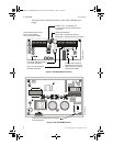
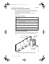
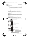
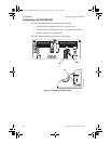
Figure 6 Typical Wiring for an ADT-APS-6R
!
J2
J9
J3
J1
TB2
JP3
JP2
Output Circuit 1: Power-limited
3 A @24 VDC (+10, –15%)
Primary Power
120 VAC or 240 VAC.
Output Circuit 1 (24 VDC)
Output Circuit 2 (24 VDC)
Secondary Power
24 VDC batteries.
Trouble Bus In/Out
Output Circuit 2: Power-limited
3 A @24 VDC (+10, –15%)
Earth Ground -
Connects to chassis or
EARTH
ground terminal on main power
supply. If two or more units are connected,
secondary units connect to earthground
on the previous ADT-APS-6R in the chain.
APS-6Rsidebrd.cdr
BATT (+)
BATT (–)
HOT
NEUTRAL
EARTH
Output Circuit 3: Non Power-limited, 6 A @24 VDC (+10, –15%)
+
–
+
–
– + – + – +
ADTAPS-6R__INSTENGLB0.fm Page 12 Tuesday, November 21, 2000 11:30 AM