


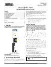
2 Issue 1 61200385L1-5A
1. If present, remove the cover plate from the appro-
priate option slot of the Total Access 850 chassis.
2. Position the module to fit in the lower and upper
grooves.
3. Slide the module into the option slot pressing
equally on the top and bottom of the faceplate until
the module is firmly positioned against the back of
the chassis.
4. Push in the ejector on the lower left-hand side of
the module to finish seating the module.
Auto-detection of Modules
The Total Access 850 RCU automatically detects the
presence of the Total Access 850 DSX-1 Module when
the module is installed into the system. You are not re-
quired to reboot.
Wiring Connections
The Total Access 850 DSX-1 Module connects to two 64-
pin Champ connectors located on the backplane. (Pi-
nouts are given in the System Manual, Section 2, Engi-
neering Guidelines.)
Faceplate LEDs
The faceplate LED colors are described below.
4. USING THE MODULE
You can configure and control the Total Access 850
DSX-1 Module from a variety of sources, including the
following:
• The terminal menus, allowing detailed configura-
tion, status, and diagnostics via the DB-9 craft port
on the front of the card, the RJ-45 craft port on the
rear of the chassis, or telnet.
The Terminal Menus
The terminal menus are available by using either a
VT-100 terminal attached to the Total Access 850 active
RCU’s craft port, the chassis’ ADMIN port, or a Telnet
session established through the RCU’s Ethernet port.
The Total Access 850 System Manual provides detailed
instructions on using any of these management ap-
proaches.
Terminal Menu Structure
The Total Access 850 uses a hierarchical menu structure
to provide access to all of its features. The top-most
menu level leads to submenus which are grouped by
functionality. All menu items display in the terminal
window.
Accessing the Module Terminal Menus
Once you are connected to a terminal, press
Enter sev-
eral times until a
LOGIN prompt displays. Enter the de-
fault, password, in lowercase characters (the login
system is case sensitive). TheTotal Access 850 upper-
level
SYSTEM INFO menu opens.
To access the terminal menu for the Total Access 850
DSX-1 Module:
1. Use the arrow keys to navigate to the
MODULES
menu and press
Enter.
2. Select the module by using the arrow keys to high-
light the specific module.
3. Press
Enter while the module slot is highlighted.
Menu options for the module now display on the terminal.
Passwords
To edit fields in the terminal menus, you must have the
appropriate password level. Each menu description in
this section indicates the password level required for
write and read access. Security level
FULL users can
view and edit every available field. Security level
STATUS users can view most fields but cannot edit.
I
NTERFACES MENU
DSX card identifies the Total Access 850 DSX-1 Module.
The following sections describe the
INTERFACES menu
options:
INTERFACE, CONFIG and TEST.
Dangerous voltage is exposed when the
cover plate is removed.
ONLINE LED Colors Description
Off No power present
Amber Channel test in progress
Blinking Amber Card initializing during
startup
Green DSX-1 signal present &
synchronized; channel is
configured for use
Red Channel alarm present
The remainder of this document describes
the menu items available when managing
the Total Access 850 DSX-1 Module via
the terminal menus.
Refer to the Total Access 850 System
Manual for detailed instructions on navi-
gating through the terminal menu.