1Section 61150087L1-5, Issue 161150.087L1-5A
Section 61150.087L1-5
Issue 1, August 1996
CLEI Code # DDMOJHD1 _ _
PRACTICES
T400 SINGLE ENVIRONMENTAL HOUSING
INSTALLATION/MAINTENANCE
C A U T I O N !
SUBJECT TO ELECTROSTATIC DAMAGE
OR DECREASE IN RELIABILITY.
HANDLING PRECAUTIONS REQUIRED.
2. INSTALLATION
The T400 Environmental Housing consists of a base,
cover, O-ring, mounting bolts for the base, mounting
bracket, lag screws and spacers for the mounting
bracket. See Figures 2, 3, 4 and 5.
The T400 Single Environmental
Housing is designed for above
ground only mounting. Never install
telephone wiring during a lightning
storm.
Install Mounting Bracket
1. Clearances between the T400 Environmental
Housing and adjacent structures must be observed
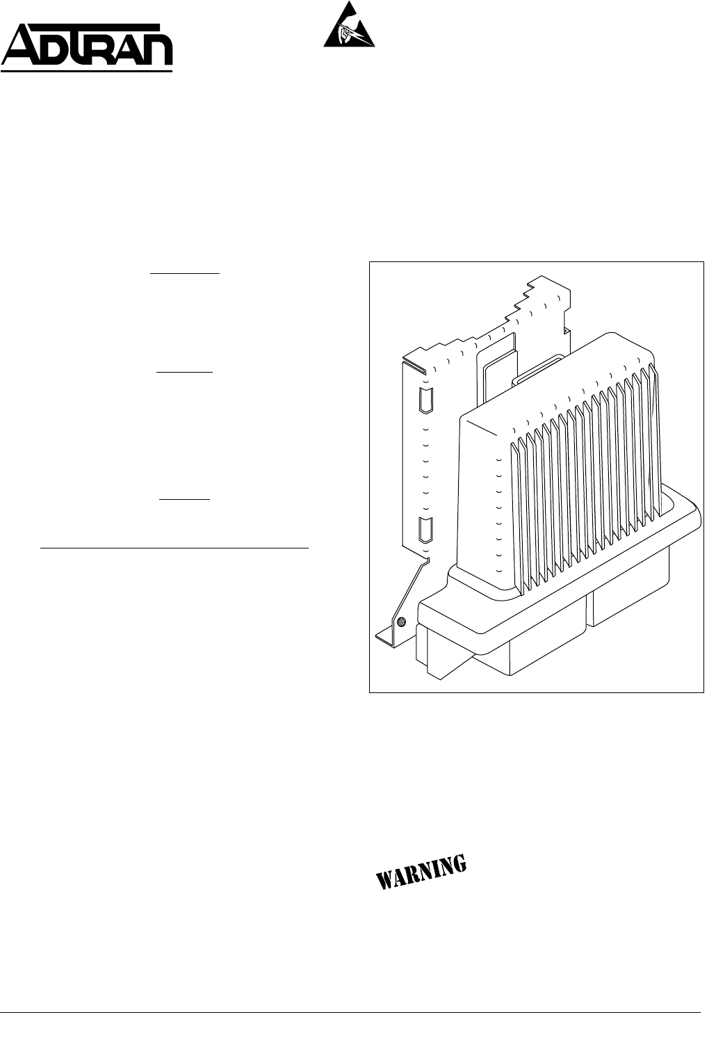
Figure 1. T400 Single Environmental Housing
1. GENERAL
This practice provides installation and maintenance
information for the ADTRAN T400 Single
Environmental Housing, part number 1150087L1.
Figure 1 is a view of the T400 Single Environmental
Housing.
Features
The basic features of the T400 Single Environmental
Housing, part number 1150087L1, include the
following:
• Houses one of the following circuit packs: FNID,
BRIDLE-R, HTU-R, HRE, or Total Reach
• Seals the T400 circuit packs from the environment
• Allows separate, unsealed access to the customer
and network wiring
• Mounts above ground to a pole or wall
• Compact T400 Environmental Housing - 9" High x
3
3/4
" Deep x 8
5/8
" Wide, 2.6 lb. with mounting
bracket
• Four replaceable gas-tube surge arrestors that
provide primary lighting protection
CUSTOMER ACCESS
NETWORK INTERFACE DEVICE
WARNING!
COVER TO BE
REMOVED BY TELEPHONE
COMPANY PERSONNEL
ONLY
CONTENTS
1. GENERAL............................................................... 1
2. INSTALLATION ...................................................... 1
3. REPLACEMENT PARTS ....................................... 4
4. MAINTENANCE ..................................................... 4
5. WARRANTY AND CUSTOMER SERVICE ........... 4
FIGURES
Figure 1. T400 Single Environmental Housing ............ 1
Figure 2. Clearances .................................................... 2
Figure 3. Mounting Holes ............................................. 2
Figure 4. Wiring Terminals ........................................... 2
Figure 5. T400 Environmental Housing Assembly....... 3
Figure 6. Surge Arrestors and the
Insertion/Extraction Tool ............................... 3
TABLES
Table A. Wiring ............................................................. 3


