PRICING AND AVAILABILITY 800.827.0807
TECH SUPPORT 800.726.8663
RETURN FOR REPAIR 256.963.8722
www.adtran.com
61212082L1-22C
For complete Installation and Maintenance: (877) 457-5007, Document #374 (P/N1212082L1) and #338 (P/N 1212083). Please have your fax number available.
DEPLOYMENT GUIDELINES
■ All loops must be non loaded
■ Actual Measured Loss (AML) not to exceed 52 dB @ 20 kHz (135 Ω termination) or 61 dB @ 40 kHz.
■ Loop length not to exceed 50 kft.
■ Maximum single bridged tap not to exceed 2 kft.
■ Maximum total bridged tap not to exceed 6 kft.
■ Maximum DC resistance not to exceed 2000 Ω.
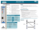
WIRING CONNECTIONS
TURNUP
1. Set dip switches on both units according to circuit design and local practices.
2. Install both TRI-C and TRI-R using standard procedures.
a) TRI-C inserts in T400 shelf, or MFT bay with MFT adapter.
b) TRI-R inserts in standard non powered T200 or T400 NCTE mounting for indoor
installations, or mounts to a wall for outdoor NID installations.
3. When inserted in an active housing the two units go through a synchronization and activation
process during which all LEDs undergo an on/off sequence.
Refer to STATUS LEDs on reverse side for LED descriptions.
4. After synchronization, which may take up to 90 seconds, the following LED indication will show:
a) ACT LED – ON
b) All other LEDs will be OFF until network occurrences cause illumination.
5. If LEDs in step 4 are as noted, proceed with loopback and BERT testing per specifications.
6. If LEDs in step 4 are in any other configuration, refer to
Troubleshooting.
7. The TRISDN system will be qualified at the 20 kHz frequency.
TOTAL REACH ISDN
REMOTE UNIT
Pair Terminal T400 Customer
Designations Pin # RJ-48
To/From Network TT, RR 41, 47 –
To Customer T, R 55, 49 4, 5
TROUBLESHOOTING
No Power at the TRI-R
■ Ensure TRI-C is supplying voltage to power the TRI-R. Measure T-R voltage at the frame (Tip to
Ground = -7 to -9 Vdc, Tip to Ring = -127 to -133 Vdc, Ring to Ground = -134 to -142 Vdc).
■ Measure T-R voltage at the TRI-R.
■ If voltage not present at the TRI-R, check continuity of cable pair.
■ If voltage is present a faulty TRI-R is indicated.
■ The TRI-R does not place a measurable short between tip and ring. Cable resistance must be
taken towards a manually applied short.
Power,but no Synchronization on TRI I/F
■ Check cable for load coils.
■ Check for excessive bridged taps.
■ Verify other deployment guidelines adhered to.
Excessive Errors on Loop
■ Compare resistance of individual conductors. If these are different, high-resistance or
intermittent opens may be indicated.
■ Check for excessive bridged taps.
■ Verify other deployment guidelines adhered to.
WARRANTY
Warranty for Carrier Networks products manufactured by ADTRAN and supplied under Buyer’s
order for use in the U.S. is ten (10) years. For a complete copy of ADTRAN’s U.S.and Canada
Carrier Networks Equipment Warranty
: (877) 457-5007, Document #414.
COMPLIANCE
Caution: Electric shock hazard. Span voltage is present on telecommunication leads (140 Vdc).


