


2 Section 61180043L1-5, Issue 1 61180043L1-5A
and two 23-inch rack mounting brackets P/N
1175048L2. This provides a complete rack mounted
battery backup solution for the Total Access 1500. In
this arrangement, the PS/BC maintains the batteries at
a peak charge of -56 V. If AC power is lost, the unit
automatically transfers power from the battery packs
without interrupting service. When AC power returns,
the unit switches back to AC power and recharges the
batteries to peak charge.
This device complies with Part 15 of the FCC rules.
Operation is subject to the following two conditions:
(1) This device may not cause harmful interference,
and (2), this device must accept any interference that
may cause undesired operation.
Changes or modifications not expressly approved by
ADTRAN could void the user’s authority to operate
this equipment.
Alarm and Battery Disconnect Relays
Two relays support Power Supply operation:
• Alarm relay
• Battery disconnect relay
Alarm Relay And Alarm Signal
The Alarm relay is provided for customer use. In
normal operation the contact alarm relay is open. If
an AC power failure occurs and the unit defaults to
the battery backup, the relay will close. The alarm
relay condition can be monitored externally using the
2-pin connection labeled “AC Alarm Output” on the
housing.
Battery Disconnect Relay
The battery disconnect relay disconnects the battery
pack from the system if the battery voltage falls below
-40 Vdc. This feature prevents damage to the
batteries. The batteries will be recharged when normal
AC voltage is restored and the relay will close when
the battery voltage exceeds -40 V.
Certain alarm features on the power supply are still
powered by the battery after the disconnect relay is
opened. These features slowly drain the battery. If it
is known that AC power will be unavailable for an
extended period (greater than a week), ADTRAN
recommends that the battery be disconnected from the
power supply to prevent over-discharge.
The batteries used in ADTRAN’s battery backup
system are designed to withstand occasional over-
discharge. While it is not recommended, the batteries
can recover their full capacity under normal charging
conditions, even when they have been subjected to
extreme over-discharge.
Fuse
A 12-amp fuse on the back panel protects the unit
from over current. The fuse isolates the AC input from
the power supply in the event of a fault. The fuse is
replaced by twisting the black cap to the left and
pulling the fuse out. After the new fuse is inserted,
the cap is pushed back in and turned to the right.
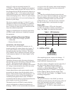
Status LED
A single multi-feature LED on the front panel
provides AC operation or battery operation power
status. See Table 1 for indication descriptions.
C A U T I O N C A U T I O N !
SUBJECT TO ELECTROSTATIC DAMAGE
OR DECREASE IN RELIABILITY.
HANDLING PRECAUTIONS REQUIRED.
3. INSTALLATION
After unpacking the unit, inspect it for damage. If
damage is noted, file a claim with the carrier then
notify ADTRAN Customer Service.
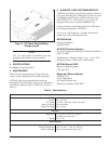
The power supply is designed to mount to the side of
the Total Access Battery Backup System P/N
1175044L1. Each power supply is designed to
maintain two Battery Backup Systems. The rack
mounting brackets P/N 1175048L2 are designed to
hold two Battery Backup Systems and the Total
Access 1500 AC Power Supply. See Figure 2 for the
mounting configuration.
Grounding
The ground connector on the PS/BC provides an
additional ground reference (the third prong of the AC
plug is also grounded) and may be connected to
“ground bus” or “ground wire” in a customer
equipment room. 18 AWG or larger ground wire is
recommended.
Table 1. LED Indication
noitarepOrewoPCAnoitarepOyrettaB
neerGKOneerG)gnigrahc(KO
wolleYliaFrewoPwolleYgnigrahcsiD
deRliaFrewoPdeR)V04-<(woL
ffOliaFrewoPffOdetcennocsiD