161175012L1-5D Section 61175012L1-5, Issue 4
Section 61175012L1-5D
Issue 4, July 2000
CLEI Code # SIUXJKAB_ _
1. GENERAL
This practice provides installation and operation
procedures for the ADTRAN Total Access
TM
750
Bank Controller Unit (BCU) common module, List 1.
The TA 750 BCU module is designed specifically for
the ADTRAN Total Access 750 and is not used in any
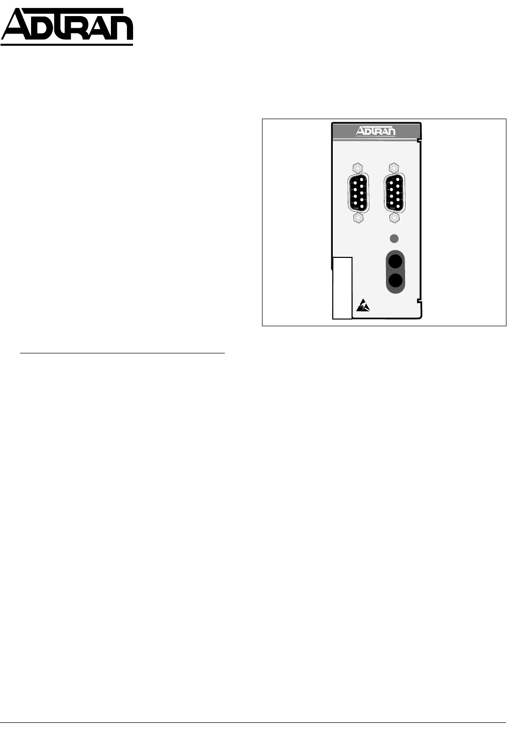
other product. Figure 1 is an illustration of the TA
750 BCU.
Revision History
This document has been revised to include Windows
Hyperterminal PASSWORD information, and update
Switch settings.
Features
The TA 750 BCU, part number 1175012L1, includes
the following features:
• Controls all common equipment and access
modules.
• T1 network termination.
• Built-in Channel Service Unit (CSU).
• Provides VT 100 craft interface via faceplate
DB-9 connector.
• Bantam Jacks provide access to Network T1.
• LED network status indication.
Figure 1. TA 750 BCU
• T1 performance monitoring.
• Supports TR-08 signaling.
• UL 1950 compliant.
• Meets NEBS Level 3 requirements.
General Description
The TA 750 BCU is a common module plug-in unit
designed for the TA 750. The BCU, with a built-in
CSU, provides all control functions for the TA 750
common units and all individual access modules. A
faceplate ADMIN DB-9 provides access for a VT 100
terminal for screen menu provisioning, and bantam
test jacks provide, transmit, and receive monitoring.
An additional TEST DB-9 provides timing for DS0
test equipment. A network LED shows status
information for the network T1. The unit is comprised
of a main circuit board and daughter card and inserts
directly in the BCU slot on the TA 750 shelf. An 8-
position DIP switch is mounted on the daughter card
and is used for T1 provisioning and clocking.
This device complies with Part 15 of the FCC rules.
Operation is subject to the following two conditions:
(1) This device may not cause harmful interference,
and (2) this device must accept any interference
received, including interference that may cause
undesired operation.
Trademarks: Any brand names and product names included in this document are
trademarks, registered trademarks, or trade names of their respective holders.
Total Access
TM
750 Bank Controller Unit
TA 750 BCU
Installation and Operation
CONTENTS
1. GENERAL ................................................................... 1
2. INSTALLATION/OPERATION .................................. 2
3. OPTIONS ..................................................................... 2
4. TESTING ..................................................................... 4
5. SPECIFICATIONS....................................................... 5
6. MAINTENANCE......................................................... 5
7. WARRANTY AND CUSTOMER SERVICE .............. 5
Figures
Figure 1. TA 750 BCU ...................................................... 1
Figure 2. Bantam Jack Monitoring Points ........................ 4
Figure 3. DB-9 Connector Pinout ..................................... 5
Tables
Table 1. Compliance Codes ............................................ 2
Table 2. DIP Switch S1 Options...................................... 3
Table 3. Pinout Connectors for RJ-48 T1 Interface ........ 4
Table 4. LED Indication.................................................. 4
Table 5. Specifications .................................................... 5
DS1
TX
M
O
N
RX
BCU
NETWORK T1
1175012L1
A
D
M
I
N
T
E
S
T
TX
RX
M
O
N
DS1


