


61200373L1-5B Issue 2, August 2001 3
Connections
All TA 850 BCU connections are made through the
backplane connector. With the exception of power and
the V.35 connector, all of the TA 850 rear panel connec-
tors terminate on the BCU. These include Network T1,
Clock source, Alarms, Fractional T1, and Management.
Refer to the TA 850 System Installation and Mainte-
nance Practice, part number 64200376L1- 5A, for addi-
tional information on rear panel connections. Table 1
describes the T1 pinout connections.
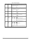
Faceplate LED
The faceplate Network LED labeled T1 Network pro-
vides status information for the network T1 using a col-
or coded message format. Refer to Table 2.
4. TESTING
The TA 850 BCU provides a variety of test options for
both the Network T1 and DS0 access modules. The face-
plate of the BCU provides a bantam jack for local T1 test
access. DS0 test access for the digital access modules
(OCU DP, DS0 DP, U-BR1TE) is provided via bantam
jacks on the faceplate of each unit.
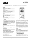
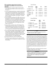
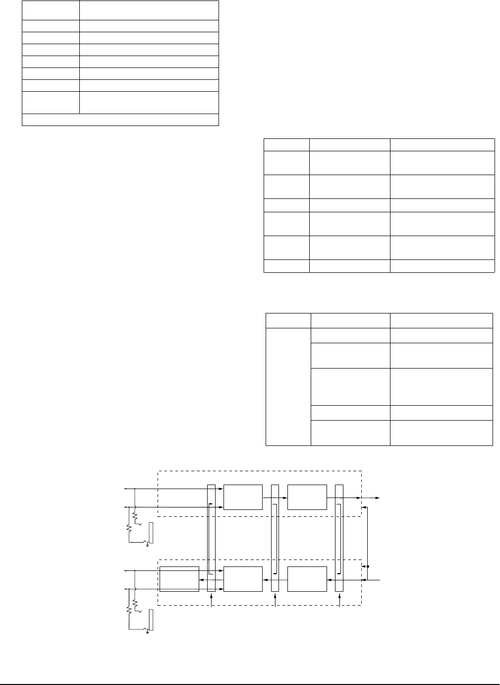
Faceplate Bantam Jack
The faceplate bantam jack provides a means to monitor
the network T1 connected to the rear of the TA 850 chas-
sis. The jacks accept standard 310-type bantam plugs.
Figure 2 on page 3 displays where the bantam jacks
monitor the T1.
Faceplate TEST connector
The faceplate DB-9 female TEST connector provides the
necessary clock output required by standard DSO Logic
Test equipment such as a TPI 108/109 test set. Specifi-
cally, the TEST connector outputs 8 kHz and 64 kHz
clock reference signal. Figure 3 on page 5 illustrates the
DB-9 TEST connector.
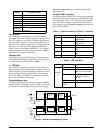
Table 1. Pinout Connectors for RJ-48 T1 Interface
Table 2. LED Indication
Figure 2. Bantam Jack Monitoring Points
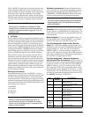
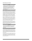
Access
Module
Maximum Number of DS0s that can
be used per module
FXS 4
FXO 4
*OCU-DP 1
*DSO-DP 1
*U-BRITE 1
*E&M 1
Nx56/64
(special slot)
24
*Supported in TA 850 Q300.
Pin Name Description
1 R1 - RING1 Receive data from
Network DS1
2 T1 - TIP1 Receive data from
Network DS1
3 unused -
4 R - RING Transmit data to Network
DS1
5 T - TIP Transmit data to Network
DS1
6, 7, 8 unused -
LED Condition Description
Network
T1
OFF No power.
RED Unit in Red Alarm (T1
down or not connected.)
YELLOW Receiving Yellow Alarm
(far end unit in Red
Alarm.)
GREEN Normal Operation.
FLASHING
GREEN
Network T1 in Test.
Clock and Data
Recovery
MON IN
Test Jack
T1
RX
PAIR
Line Format
Decoder
To
Backplane
Receiver Circuitry
Transmitter Circuitry
MON OUT
Test Jack
Local
Loopback
Point
T1
TX
PAIR
From
Backplane
Line
Loopback
Point
Payload/CSU
Loopback
Point
Equalizer
Line Format
Encoder
DJAT
T1
R1
T
R