


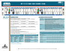

BCU LEDs
Indicator Color Description
AY Amber ON indicates a Yellow Alarm is being received from the T1 carrier facility
AR Red ON indicates the BR1/10 side is in a Red Alarm condition
TP Amber ON indicates Trunk Processing is active on all U-BRITEs (10)
RCV Red ON indicates a loss of framing of T1 signal from the T1 carrier facility
ESF Green ON indicates the T1 Extended SuperFrame format is selected
SF Green ON indicates the T1 SuperFrame format is selected
B8ZS Green ON indicates T1 B8ZS line coding is selected
AMI Green ON indicates T1 AMI line coding is selected
10DSL Green ON indicates D Channel 4:1 TDM mode is selected to transport 10 BRIs
8DSL Green ON indicates TR-397 3-DS0 framing across the T1 facility to transport 8 BRIs
EXT Green ON indicates External timing input is selected (BITS)
LOC Green ON indicates BR1/10 side is using a locally generated clock source to time the
T1 network
LOOP Green ON indicates BR1/10 clock is recovered clock from the T1 network
CAU Green ON indicates clock is recovered from the DSL position #1 to time the T1 network
DS1-LOC Green ON indicates the BR1/10 side is in a Local DS1 Loopback
RMT Green ON indicates the unit has initiated remote DS1 loopback when set in ESF mode
FLASHING indicates it responded to remotely commanded loopback, or has
provided a loopback path for the T1 data-stream in SF mode
LP-SYNC* Red ON indicates the U-interface is out of sync for the selected channel unit
LP-CRC* Red In normal operation flashes upon receiving NEBEs from the loop. In Local PM
mode flashes 6-19 CRCs and is solid when >20 CRC errors are detected from the
loop
CR-SYNC* Red ON indicates no TR-397 framing across the T1 carrier for the selected channel
CR-CRC* Red In normal operation flashes upon receiving NEBEs from the T1 carrier. In Local
PM mode flashes 6-19 CRCs and is solid when >20 CRC errors are detected
from the T1
DS0-LB* Amber ON indicates the selected U-BRITE is in a 2B+D commanded eoc loopback.
Flashing once per second=B1 is looped, flashing twice per second=B2 is looped
ACT* Green ON indicates the customer’s NT1 has successfully exchanged ACT bits with the
network for the selected channel
* Status is for the channel unit selected on the DSL 10-position rotary switch on the LIU of the the
BR1/10 side
WARRANTY
Warranty for Carrier Networks products manufactured by ADTRAN and supplied under Buyer’s
order for use in the U.S. is ten (10) years. For a complete faxback copy of ADTRAN’s U.S. and
Canada Carrier Networks Equipment Warranty, call (877) 457-5007, Document #414.
PRICING AND AVAILABILITY 800.827.0807
TECH SUPPORT 800.726.8663
RETURN FOR REPAIR 256.963.8722
www.adtran.com
61150081L2-22A
BR1/10 2X MINI ISDN CHANNEL BANK
5
4
3
2
1
9
8
7
6
ADR3
ADR2
AD
R1
NT1
LPTX
LPBX
AD
R6
AD
R5
ADR4
10
CRTX
T
E
S
T
IN
M
O
N
O
U
T
LIU
1150079L
2
ON
1 2 3
4
5 6 7 8 9 10
BCU
1 2 3 4
TEST
AY
TP
ESF
B8ZS
10DSL
EXT
LOOP
DS1-LOC
LP-SYNC
CR-SYNC
DSO-LB
AR
RCV
SF
AMI
BDSL
LOC
CAU
RMT
CRC
CRC
ACT
LB ON
REMOTE
DS0
B2
OFF
LOC
DS1
B1
115
00
8
0
L
1
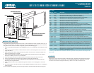
Channel Selection
Loopback Address
DB-9 Connector
BCU DIP Test Switch
Recessed Test Push Button
Bantam Jacks
LOOPBACK TEST (ADR6, NT1)
Loopbacks in the network to customer direction can be initiated from either the ISDN switch (eoc) or
the BR1/10 LIU and BCU. The down-stream direction is automatically selected based on the channel
unit position in the circuit. To initiate a loopback, perform the following steps:
1. Insert TX and RX bantam plugs of the DS0 digital test set (i.e. TPI 108/109) to the TEST jacks of the
LIU
2. Connect test set clock interface to DB9 connector of the LIU and configure the test set for Near
Logic and 64kb/s
3. Select the desired U-BRITE using the DSL rotary switch on the LIU( the selected U-BRITE LED
flashes red and green for 3 seconds
4. Select the desired loopback address using the address rotary switch on the LIU (note: ADR1 is
always the U-BRITE your test set is connected to
5. Select DS0 option and select the desired Bearer channel B1/B2 dip switches on the BCU
6. Press the recessed TEST push-button on the BCU to initiate the loopback test
7. The DS0 LB status LED on the BCU will illuminate if the loopback is successful and will not
illuminate if the loopback failed
8. Send and Receive 2047 to the established loopback and observe the DS0 digital test set for bit
errors
9. It is not necessary to exit the test mode to select additional addresses (ADR2, NT1) or to change to
B1/B2 channels
10. To terminate the loopback, press the TEST push-button and the amber DS0-LB LED will go out