


INDICATIONS AND PROBABLE CAUSES
Front Panel or Circuit Parameters Indicate Abnormal Operation
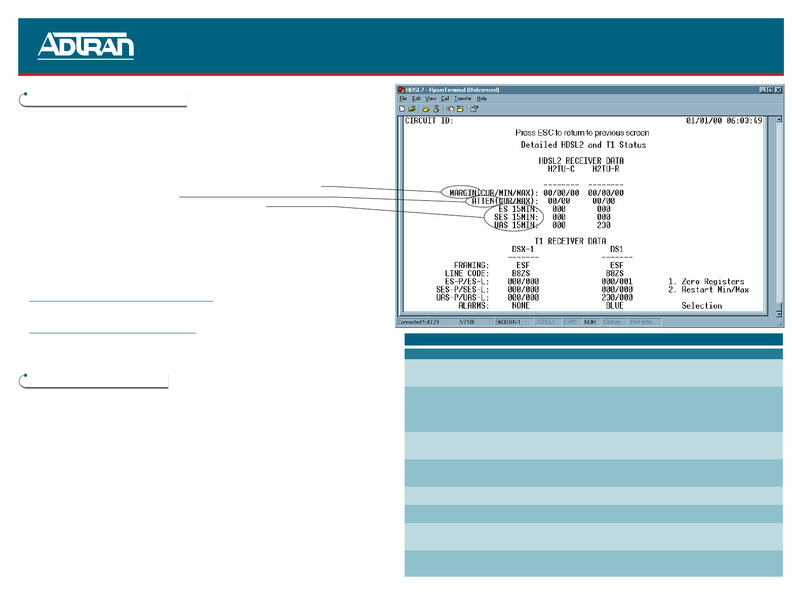
Connect a terminal or PC to the RS-232 (DB-9) craft interface located on the faceplate. The
terminal must be VT100 or compatible and set for 1.2 to 19.2 kbps, 8 data bits, no parity, 1
stop bit, and no flow control. Select “3” from the ADTRAN HDSL2 Main Menu Screen and “2”
from the Span Status Screen:
■ Is signal quality fluctuating (this would occur when real-time mode is active)?
■ Is ATTEN (pulse attenuation) > 30 dB?
■ Are there any errors counting on the ES, SES, or UAS registers?
If the above conditions do not exist, the circuit should provide quality service; however, if any
of the above conditions exist, a cable problem or excessive loss situation is probable and
more detailed cable testing should be done to verify all HDSL2 Loop Specifications are met.
These conditions may also reflect intermittent cable faults or excessive noise impairments. If
intermittent faults or noise impairments are suspected, select “5” from the HDSL2 Main
Menu and review the Performance History Screen.
F
ront Panel Indications Under Normal Operation
STATUS ● Green
Circuit Parameters Under Normal Operation
■ LOSS < 30 dB
■ Good signal quality with no fluctuation
■ All HDSL2 Deployment Guidelines are met
HDSL2 DEPLOYMENT GUIDELINES
■ Cable pairs must be non-loaded
■ Total bridged tap < 2.5 kft
■ No single bridged tap >2 kft
■ 196 kHz insertion loss ≤ 35 dB
■ Pulse attenuation (loss on HDSL2 Span Status Screen) ≤ 30 dB
■ Maximum loop resistance is 900 Ω
■ Impulse noises < 50 dBrn as measured using a 50 kb filter
■ Wideband noise ≤ 31 dBrn as measured using a 50 kb filter
For further information regarding deployment guidelines and applications, reference
ADTRAN’s Supplemental Deployment Information for HDSL/HDSL2 document,
P/N 61221HDSLL1-10.
HDSL2 TROUBLESHOOTING GUIDE
PRICING AND AVAILABILITY 800.827.0807
TECH SUPPORT 800.726.8663
RETURN FOR REPAIR 256.963.8722
www.adtran.com
61222003L2-22A
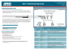
HDSL2 Loopback Control Codes
Name Code Comments
Arming (In-band) 11000 Signal sent in-band or over ESF data link. HDSL2 elements in disarmed
Arming (ESF) 0001 0010 1111 1111 state make transition to armed state. Detection of either code results in
(12 FF Hex) Smartjack loop up, if NIU loopback is enabled.
Activation 1101 0011 1101 0011 Signal sent in-band. HDSL2 elements in armed state make transition to
(H2TU-C) (D3D3 Hex) loop up state. Loop up state timeout is programmable from the H2TU-C.
Activation 1100 0111 0100 0010
(H2TU-R) (C742 Hex)
Deactivation 1001 0011 1001 0011 Signal sent in-band. HDSL2 element loop-up state makes transition to
(9393 Hex) armed state.
Disarming (In-band) 11100 Signal sent in-band or over ESF data link. HDSL2 elements in any state
Disarming (ESF) 0010 0100 1111 1111 make transition to disarmed state.
(24FF Hex)
Arming Timeout N/A 2 Hours
Loop-up Timeout N/A HDSL2 element in loop up makes transition to armed state.
Programmable from H2TU-C: None, 20, 60, or 120 minutes.
Loopback Timeout 1101 0101 1101 0110 Signal sent in-band. Sets Loopback Timeout to NONE. Timeout will
Override (D5D6 Hex) return to previous value when pattern is removed. Arming pattern
(11000) must precede this pattern.
Span Power 0110 0111 0110 0111 Signal sent in-band. Disables span powering of remotes. Span power
Disable (6767 Hex) will return when pattern is removed. Arming pattern (11000) must
precede this pattern.