


61212075L1-5C Section 61212075L1-5, Issue 3 3
In this case the (red) power wire is connected to the
48V(+)/GND terminal and the (black) return wire to
the 48V(-) terminal. The green wire connects to the
Frame Ground terminal (see Figure 4).
CAUTION
Terminate grounds to an approved ground
location. Check metal to metal contact on all
ground connections, ensure ground circuit
continuity.
Standalone Ground Option
Optionally, frame ground is provided by a ground lug
on the standalone motherboard (J1). J1 and TB1 are
electrically connected. A ground wire portal on the
rear panel of the housing provides access for this
ground wire. J1 is a screw compression terminal
requiring a solid copper wire connection.
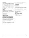
Shelf Power
The 12-slot shelf backplane has a dual power terminal
(TB1) with connections for -48V A, -48V RET A,
-48V B, and -48V RET B, plus a common Frame
Ground connection (see Figure 5). A backplane diode
arrangement allows both DC supplies to load-share
with one side picking up the entire load should the
other side fail.
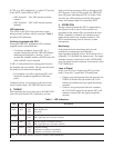
Figure 3. Standalone Power Connection
Fuse
The -48 VDC is fused on each NIU3 card.
Options
Line Build Out
A 2-position DIP switch (SW2) on the NIU3 enables
signal attenuation towards both the network and the
customer. DIP switch option selection must be made
prior to inserting the NIU3 into the host circuit board.
If network equipment (e.g. ADM) is within 225 line
feet of the NIU3, enable LBO on SW2-1.
• SW2 Position 1 – ON, LBO toward network
enabled
• SW2 Position 1 – OFF, LBO toward network
disabled
RETURN
SUPPLY
TB1
48V(+)/GND
48V(-)
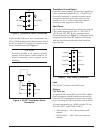
Figure 5. Shelf Power Connection
-48V A
A RETURN
A SUPPLY
B SUPPLY
B RETURN
FRAME
GROUND
TB1
-48V RET A
-48V B
-48V RET B
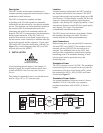
Figure 4. AC/DC Transformer Power
Connection
48V(+)/GND
GRN
RED
BLK
TB1
48V
200mA
48V(—)