


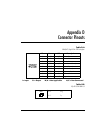

Appendix D: Connector Pinouts
144 Express XL/XLT User Manual 61200070L1-1
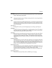
Table D-C
RJ-11 POTS
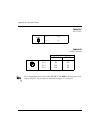
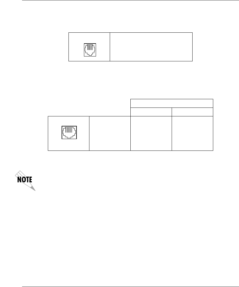
Table D-D
10BaseT Ethernet
The switch position can be set for either TO NIC or TO HUB on the back panel of the
Express XL/XLT. The rear panel is illustrated in Figure 1-7 on page 18.
Pin 3 Ring
Pin 4 Tip
Switch Position
TO NIC TO HUB
Pin 1 TX1 RX1
Pin 2 TX2 RX2
Pin 3 RX1 TX1
Pin 6 RX2 TX2
PHONE
10BT