


HDSL4 TROUBLESHOOTING GUIDE
PRICING AND AVAILABILITY 800.827.0807
TECHNICAL SUPPORT 800.726.8663
RETURN FOR REPAIR 256.963.8722
www.adtran.com
61222426L1-22C
LOOPBACK AND CONTROL CODES
Pattern Description Requires Arming?
1in3 Loop down all units and disarm. No
2in5 Arming Pattern, H4TU-R will loop up if Smartjack LB is enabled. No
3in5 Disarm and loop down all units. Restores LB TMO after D5D6. No
1in6 Network Arming Pattern. If Smartjack LB is enabled, HTU-R will loop toward network. No
2in6 H4R LB to Network. No
3in6 H4R LB to Network. No
4in6 H4R LB to Customer. No
5in6 H4R LB to Customer. No
3in7 H4TU-R LB to Network. No
4in7 H4TU-C LB to Network. No
5in7 H4TU-R LB to Customer. No
6in7 H4TU-C LB to Customer. No
3F1E H4TU-C LB to Customer. No
3F02 H4TU-R LB to Customer. No
3F04 H4R LB to Customer. No
3F06 H4R LB to Customer. No
6767 Disable span powering while present. Yes
9393 Loop down H4TU-C, Repeaters - all loopbacks. Loop down H4TU-R - Cust LB always.
Will only loop down H4TU-R Network LB if NIU is disabled. Does not disarm units if they are
armed. No
C741 H4R #1 loop up pattern. 10 bit error injection. Yes
C742 H4TU-R loop up pattern. 20 bit error injection. Yes
C754 H4R #2 loop up pattern. 200 bit error injection. Yes
D3D3 H4TU-C loop up pattern. 231 bit error injection. Yes
D5D5 Query Loopback Pattern (error injection)
H4TU-C: 231 Errors, H4R #1: 10 Errors, H4R #2: 200 Errors, H4TU-R: 20 Errors No
D5D6 Loopback Timeout Override: Disables LB timeout. Restores original LB timeout when unit
is disarmed. Yes
FF48 FDL Arming Pattern (ESF only). Arms all units, H4TU-R will LB to Network if NIU Enabled
(if pattern sources at network). No
FF24 FDL Disarm Pattern (ESF only). Loop down and disarm all units No
FF1E H4TU-C LB to Network. Will not loop up H4TU-C if H4TU-C already in LB to Customer. No
FF02 H4TU-R LB to Network. Will not loop up H4TU-R if any unit already in LB to Customer. No
FF04 H4R LB to Network. No
FF06 H4R LB to Network. No
WARRANTY
ADTRAN will replace or repair this product within the warranty period if it does not meet its published
specifications or fails while in service. Warranty information can be found at www.adtran.com/warranty.
U.S. and Canada customer Faxback: 877-457-5007, Document 414.
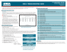
ADTRAN HDSL4 equipment is designed with troubleshooting-at-a-glance features. The following information provides
suggestions for troubleshooting as a result of LED indications which are indicative of loop trouble.
NOTE: Pressing “ESC” while on any screen will go back to the previous screen.
INDICATIONS AND POSSIBLE CAUSES
DSL LED Red
Connect a terminal or PC to the RS-232 (DB-9) craft interface on the front panel. The terminal must be VT100 or compatible
and set for 1.2 to 19.2 kbps, 8 data bits, no parity, 1 stop bit, no flow control. Select “3” from the ADTRAN HDSL4 Main Menu
screen and “1” from the Span Status Screen. Verify the following conditions on the HDSL4 and T1 Detailed Status Screen:
■ Margin ≥ 3 dB
■ Attenuation ≤ 35 dB (1st segment)
Attenuation ≤ 31 dB (2nd segment)
■ No ES, SES, or UAS (Performance History Screen, Main
Menu Selection 5)
If the above conditions do exist, the circuit should provide
quality service; however, if any of the above conditions do not
exist, a cable problem or excessive loss situation is probable,
and more detailed cable testing should be done to verify all
HDSL4 loop specifications are met. These conditions may also
reflect intermittent cable faults or excessive noise impairments.
If intermittent faults or noise impairments are suspected, review
the Performance History Screen.
HDSL4 DEPLOYMENT GUIDELINES
The guidelines provided below apply to the segments of an
HDSL4 circuit, as follows:
1st segment = between the H4TU-C and H4R
2nd segment = between two H4Rs or single H4R and H4TU-R
3rd segment = between the second H4R and the H4TU-R
These deployment guidelines provide the basics for HDSL4 circuit provisioning. If these parameters are met, then the circuit
will provide quality service. If not, a cable problem or excessive loss situation is probable. In this case, a more detailed cable
analysis is required to ensure that all HDSL4 loop specifications are met. These conditions may also be the result of
intermittent cable faults or intermittent noise impairments. If intermittent problems are suspected, utilize the Performance
History screen to assist in troubleshooting.
1. All loops are nonloaded only
2. Any single bridged tap is limited to 2 kft.
3. Total bridged tap length is limited to 2.5 kft.
4. Bridge tap within 1000 feet of units may affect performance of the
circuit
5. Margin ≥ 6 dB (Detailed Status Screen)
6. No ES, SES, or UAS (Performance History Screen)
7. Foreign Voltage DC (t-r, t-g, r-g) < 3 VDC
8. Insulation Resistance (t-r, r-g, t-g) > 3.5 MΩ
9. Impulse Noise ≤ –40 dBmF (measured with an F filter)
10. Wideband Noise ≤ –54 dBmF
11. Longitudinal Noise (Power Influence) < 80 dBrnC OK
80–90 dBrnc Marginal
> 90 dBrnc Unacceptable
NOTE: The insertion loss reading shown on the Detailed Status
Screen is an approximation that is valid for some loops.
Exercise caution when using this value.
Range Limits: 26 Gauge / 70ºF / PIC
Recommended Maximum
(DSL Assistant Green Zone)
1st segment 10.8 kft.
2nd/3rd segment 10.55 kft.
Range Limits: 24 Gauge / 70ºF / PIC
Recommended Maximum
(DSL Assistant Green Zone)
1st segment 15.25 kft.
2nd/3rd segment 15.05 kft.
Attenuation Limits
Recommended Maximum
(DSL Assistant Green Zone)
Upstream Downstream
1st segment 31 dB 33 dB
2nd/3rd segment 30 dB 30 dB
NOTE: In three segment circuits (two H4Rs),individual
segment resistance values must be verified. Refer
to the HDSL4 Deployment Guidelines section of
the Installation and Maintenance Practice
(P/N 61222426L1-5x) for those guidelines.