


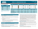
INSERTION LOSS MEASUREMENTS
10000 15.00
50000 25.50
100000 30.00
150000 32.75
196000 35.00
200000 35.25
NOTE: If your TIMs is unable to transmit 200 kHz tone,
set the TIMs to one of the frequencies shown above and
compare the received signal to the maximum loss at that
frequency.
Turn-up Guide
1. Set option switches according to circuit design and local practice.
2. Install HTU-C and HTU-R.
3. See reverse side of this job aid to ensure all LEDs are correct and synchronization has occurred.
a) HTU-C will have red ALM LED if not connected to network. LP1 and LP2 should be solid
green.
b) HTU-R will have red ALM LED if no customer connected. LP1, LP2, line coding and framing
(if not UNFR) LEDs should be illuminated.
4. If all LEDs are correct:
a) Verify that the signal quality is the same on each loop. Ensure signal quality indicators do
not fluctuate.
b) Verify that the loop loss is within design limits. If there is a difference of more than 1 dB
between the two loops, a problem exists with the cable pairs.
c) If errors occur, use the Current System Status and Performance History screens to determine
where they are occurring. See Troubleshooting Guide section.
5. If everything checks out, proceed with BERT testing.
Troubleshooting Guide
The HTU-C DSX LED is Flashing,but no Errors are Indicated by the HTU-R
■ A BPV, Frame Error (SF) or CRC Error (ESF) has been detected at the DSX-1 interface. Possible network
or wiring problem between the HTU-C and the DSX. This is not an indication of problems on the
HDSL loops.
The HTU-R DS1 LED is Flashing,but no Errors are Indicated by the HTU-C
■ A BPV, Frame Error (SF) or CRC Error (ESF) has been detected at the DS1 interface. This indicates a
wiring problem or a B8ZS/AMI mismatch between the HTU-R and the customer equipment. This
is not an indication of problems on the HDSL loops.
Frequency Maximum
(kHz) Loss Data (dB)
The HTU-R has Power,but LP1 and LP2 LEDs are Dark.The Unit cannot Sync with the HTU-C
■ Simplex power for powering the HTU-R can be passed over cable pairs that contain load coils or
that are too long for HDSL synchronization. Using a TIMs, verify the circuit is within design limits.
■ The HTU-R will power up as long as there is at least one good conductor on each loop. To test,
remove the protector plug at the MDF and measure t-r resistance to the HTU-R on both loops.
The HTU-R will place a 3 ohm short between t-r on both loops. An extremely high impedance
indicates an open conductor. An extremely low reading on one loop may indicate a t-r short in
the field. In the field, measure t-t and t-r voltage with the HTU-C installed and compare to the
chart above. If these voltages are not present, open pairs or mis-wiring is indicated. As with other
circuits, standard resistance measurements between each conductor and ground should also be
used to test for a grounded conductor.
■ If the HTU-C is optioned for LV and there are two HREs in the circuit, the HTU-R could fail to
power up normally. The LEDs on the HREs or HTU-R will flash at a rate of 3 times/second. Make
sure the voltage option on the HTU-C is set to HV.
■ A high resistance open which degrades to the point that it causes the circuit to lose sync can
be “resealed” by reseating the HTU-C. Test the cable pairs before reseating the HTU-C.
Running Excessive Errors on the Loop
■ Measure t-r resistance as described above. If the pairs are unbalanced by more than 4 ohms, or
a measurement varies a great deal, this could indicate a high resistance open or an intermittent
fault on the loop with the higher measurement. A TDR is typically required to locate this splice
for repair.
■ Excessively long bridged taps can also cause errors. Check the records and/or use a TDR to verify the
location and length of bridged taps.
■ Using ADTRAN’s “Performance History” screen, it is often possible to see that many more errors
are being received on a particular loop or at a particular unit. The fault will typically be very close
to the unit receiving the most errors.
No Power at the HTU-R
■ This could be caused by a loop with two open conductors. Measure t-r resistance from the MDF
to the HTU-R or use the voltage chart to see which pair is open.
■ Check the HV/LV option on the HTU-C and re-option if necessary.
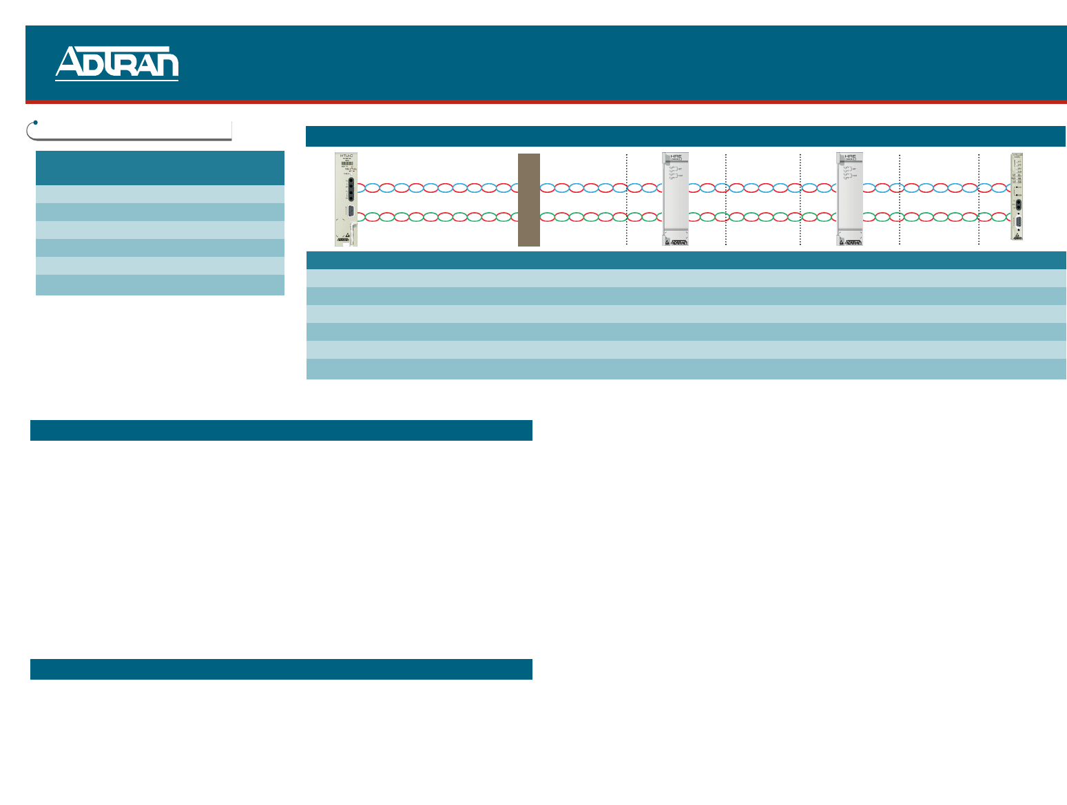
HTU-C VMDF HRE 1 HRE2 HTU-R
AB CD EF
t-t Voltage t-t Voltage t-t Voltage t-t Voltage t-t Voltage t-t Voltage
Open at Frame HV 185 - 190 N/A N/A N/A N/A N/A
Open at Frame LV 145 - 150 N/A N/A N/A N/A N/A
HTU-C LV / HTU-R 145 - 150 145 - 150 130 - 145 N/A N/A 125 - 130
HTU-C LV / HRE1 / HTU-R 130 - 135 110 - 135 110 - 135 N/A N/A 100 - 135
HTU-C HV / HRE 2 / HTU-R 185 - 190 160 - 185 160 - 185 140 - 185 140 - 185 130 - 185
NOTE: All measurements taken with HTU-C installed.With the HTU-C unseated or with protector removed at VMDF,t-r resistance will be cable resistance plus 3 ohms
(for either HRE or HTU-R).
TURN-UP & TROUBLESHOOTING GUIDE
Pricing and Availability 800.827.0807
Tech Support 800.726.8663
Return for Repair 256.963.8722
www.adtran.com
61245004L6-22B