


Quick Start Guide, 61200740L1-13A, March 2006 Technical Support 1-888-4ADTRAN (1-888-423-8726) Copyright © 2006 ADTRAN, All Rights Reserved
For more detailed documentation, visit us online at www.adtran.com.
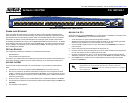
Quick Start Guide
®
NetVanta 1355 PWR P/N 1200740L1
CONFIGURE THE UNIT’S IP ADDRESS
The following steps create an IP address and subnet mask for the ETH 0/0 interface and add a
default route to the route table.
1. At the # prompt, enter config terminal.
2. Enter enable password password
to assign an Enable Security mode password. This is
necessary for Telnet configuration sessions.
3. Enter interface eth 0/0 to access the Ethernet port on the rear panel of the unit.
4. Enter ip address 10.10.10.1
255.255.255.0 to assign an IP address to the Ethernet port using
a 24-bit subnet mask. Contact your Network Administrator to obtain the IP address (and
subnet mask) for your particular configuration.
5. Enter no shutdown to activate the interface to pass data.
6. Enter exit to exit the interface commands and return to the Global configuration mode.
7. Enter ip route 0.0.0.0 0.0.0.0 10.10.10.2
to add a default route to the route table. Contact
your Network Administrator to obtain the IP address of your default gateway.
ENABLE TELNET ACCESS
The following steps create a password of adtran for Telnet access. By default, Telnet access is
enabled with a password of password.
1. Verify that the prompt of your unit displays (config)#.
2. Enter line telnet 0 4 to change the configuration parameters for the Telnet sessions.
3. Enter login to initiate Telnet access.
4. Enter password adtran
to change the login password for the Telnet sessions.
5. Enter exit to return to the Global Configuration mode.
6. Verify that the prompt of your unit displays (config)#.
7. Enter do write memory to save the current configuration.
Important: For additional details on product features, specifications,
installation, and safety, refer to the appropriate Hardware Installation
Guide on the ADTRAN OS System Documentation CD shipped with the
base unit and available online at www.adtran.com.
CONFIGURE YOUR APPLICATION
More detailed documentation for configuring your ADTRAN unit is provided on the ADTRAN OS
System Documentation CD included in your shipment. For more detail on hardware setup, refer to
the appropriate NIM Quick Start Guides and the Hardware Installation Guide. For more detail on
configuring your system, refer to the ADTRAN Operating System (AOS) Command Reference
Guide, configuration guides, and technical support notes.
ETHERNET PINOUTS
Pin Name Description
1 TX1 Transmit Positive
2 TX2 Transmit Negative
3 RX1 Receive Positive
4, 5 — Unused
6 RX2 Receive Negative
7, 8 — Unused
CONSOLE PINOUTS
Pin Name Description
1 DCD Data Carrier Detect (output)
2 RD Receive Data (output)
3 TD Transmit Data (input)
4 DTR Data Terminal Ready (input)
5 SG Signal Ground
6 DSR Data Set Ready (output)
7 — Unused
8 CTS Clear to Send (output)
9 — Unused
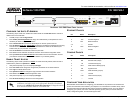
CF
SLOT 1 SLOT 2
ANALOG STA ANALOG TRK
0/1 0/2 0/1 0/2
MOH
NCNO
COM
ETH 0/0
CONSOLE
DOOR
RELAY
100-250 VAC
50-60Hz
PAGE
NETVANTA 1355 PWR REAR PANEL LAYOUT