LED STATUS
STATUS●● Off No power to unit
● Green Power up and initialization OK
● Yellow Unit is in Out-of-Service – Unassigned mode
✷ Flashing Yellow Unit is in Out-of-Service – Maintenance mode
● Red Unit has an equipment failure
OPTICS ● Green Normal Operation
● Yellow Soft failure (e.g. RDI)
✷ Flashing Yellow Unit in Test (e.g. Loopback)
● Red LOS, LOL, or other hard alarms on optical
interface
✷ Flashing Red Unit in Test (e.g. Loopback) with an alarm present
on the Optical Interface
DS3 ●● Off DS3 disabled
● Green DS3 normal operation
● Yellow Soft failure (e.g. RDI)
✷ Flashing Yellow Unit in Test (e.g. Loopback)
● Red LOS, LOL, or other hard alarms on DS3 interface
✷ Flashing Red Unit in Test (e.g. Loopback) with an alarm present
on the DS3 Interface
CRAFT INTERFACE
■ Connect to terminal using a serial cable with a male DB-9 connector.
■ Set VT100 terminal emulation to 9600 bps, 8 Data Bits, No Parity, 1 Stop Bit,
and No Flow Control.
■ Baud rate is configurable at 9600, 19,200, 38,400 or 115,200 bps.
DESCRIPTION
The OPTI-T200 is designed to work in a back-to-back mode of operation,
OPTI-T200 to OPTI-T200. It uses a standard 1310 nm OC3 signal to interface
between the systems and provides a single DS3 signal to the loop. The
OPTI-T200 provides DCC communication with TL1 support. A craft port and
an Ethernet port are available on the front panel for management. The
OPTI-T200 is a T200 mechanics card, which will fit standard T200 and T400
enclosures.
Compliant with SONET standards, the OPTI-T200 functions as a terminal
multiplexer, detecting standard optical, SONET, and DS3 related alarms and
conditions. The OPTI-T200 is easily managed with TL1 or TCP/IP commands,
or Telnet sessions separately to each system or via the craft interface.
OR DECREASE IN RELIABILITY.
HANDLING PRECAUTIONS REQUIRED.
■ For a complete Installation and Maintenance Practice (P/N 61184400L1-5): 877-457-5007, Faxback Document 918. Please have your fax number ready. ■
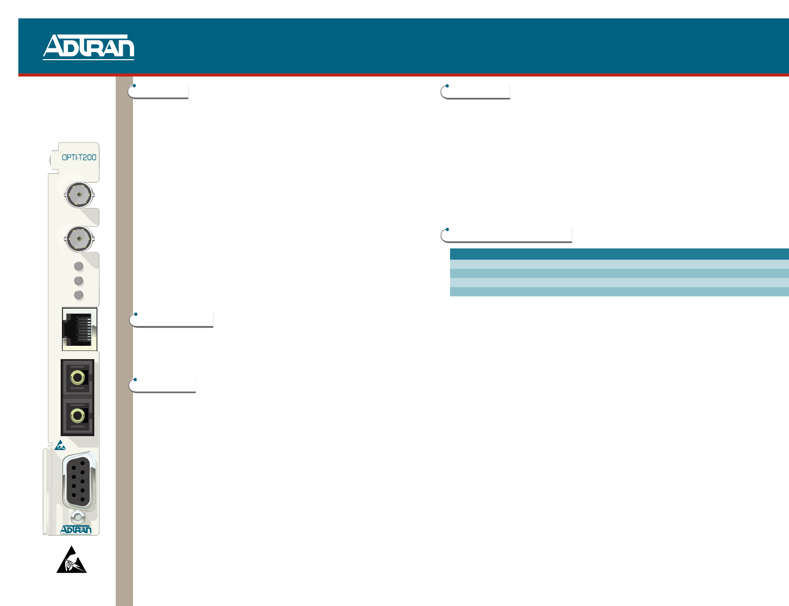
INSTALLATION
The OPTI-T200 is a T200 mechanics card which will fit standard T200 and T400 enclosures.
Ensure the appropriate chassis is installed before proceeding with the installation.
Carefully insert the OPTI-T200 halfway into the selected slot. Route the fiber cables to the
front panel and approximately 4 inches past the SC receptacles (to create slack). Gently but
firmly push the OPTI-T200 all the way into the slot, being careful not to pinch the fibers
between the front panel and the shelf.
WARNING: Once fully inserted into the chassis, the module will be powered (provided power
is connected to the chassis).
When the OPTI-T200 powers up, it performs a self-test. The front panel LEDs illuminate for
approximately 8 seconds. The self-test is complete once the STATUS LED illuminates
Green.
ALARM CONTACT DEFINITION
Lead Assignment Contact (functionally) * Contact Rating
T (pin 7) Failure detected on optical facility Normally Open 60 VDC
R (pin 13) 0.2 A
T1 (pin 41) Failure detected on coax facility Normally Open 1M cycles (min)
R1 (pin 47) −40ºC to +65ºC (temp)
NOTE: Simultaneous T/R & T1/R1 contact closures used to indicate internal unit failure, loss
of OC-3/DS-3 inputs, or loss of power.
POWER: –48VR = Pin 17, –48VDC = Pin 35, Frame-GND = Pin27.
1
2