


Page 361291021L5-5A Section 61291021L5-5A, Issue 1
The unit should be wired as follows:
• Network pair to terminal strip TT and TR positions
• To Customer and From Customer pairs through
customer 8-pin modular connector
or
To Customer (DRT, DRR) and From Customer
(DTT, DTR) to designated terminal strip positions
No rate selection is necessary for the TRDDS-R. The
unit automatically adapts to the service rate of the Total
Reach dataport in the Central Office (CO).
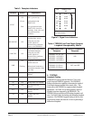
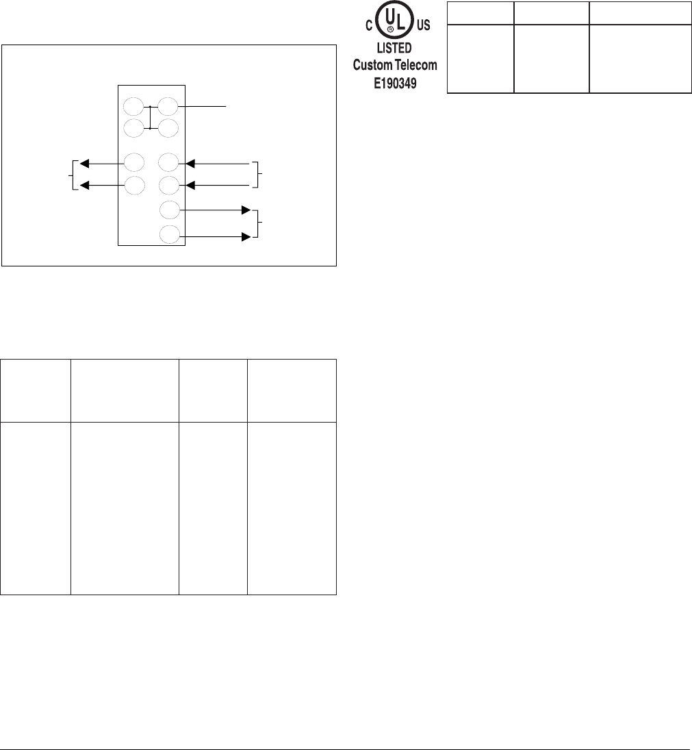
Electrical Code Compliance
Table 2 shows the UL/CUL Telecommunications Codes
for the TRDDS-R. The TRDDS-R complies with the
requirements covered under UL 1459 third edition and is
intended to be installed in an enclosure with an
Installation Code (IC) of “B” or “E”. The TRDDS-R is
intended for installation in restricted access locations
only.
Display Indicators
The TRDDS-R contains faceplate-mounted LED
indicators which display the operating status and service
rate. The indicators are described in Table 3.
Signal Meter
The TRDDS-R contains a signal meter that approximates
the amount of dB loss on the TRDDS loop at 13.3 kHz
(135 Ω termination), the Nyquist frequency of TRDDS.
The signal meter on the TRDDS-R may be used to verify
that the loop loss is actually within TRDDS deployment
guidelines without the requirement of peripheral test
equipment. The signal meter is activated automatically
upon power up during the TRDDS training sequence and
remains activated until synchronization occurs (usually
30-90 seconds after power-up). For example, if the signal
meter only illuminates the 2.4 LED, then the loop loss is
too great for TRDDS deployment. If the signal meter
illuminates 2.4 and 4.8 (only two LEDs), then the
TRDDS loop loss is between 50 and 56 dB and the loop is
considered marginal for TRDDS deployment. If three or
more rate LEDs are illuminated during TRDDS train-up,
then the circuit is considered to be within TRDDS
deployment guidelines. See Figure 5 for a translation of
the signal meter loss ranges in dB. If the loop loss
indicates a marginal loop for TRDDS deployment, then a
more precise loop loss measurement can be made with the
appropriate test equipment.
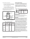
Table 1. Wiring Connections
riaP
lanimreT
pirtS
snoitangiseD
004T
niP
rebmuN
remotsuC
84JR
morF/oT
krowteN
RT,TT74,14
oT
remotsuC
)xR(
RRD,TRD51,58,7
morF
remotsuC
)xT(
TTD,RTD55,942,1
TUPNITUPTUO
CIA -
CTX X
CPC C
Table 2. UL/CUL Telecommunications Codes
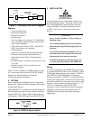
Figure 4. Circuit Card Pin Assignments
1
17
Frame Ground
(TT)
(DTT)
(TR) (DTR)
(DRT)
TRDDS-R
15
(DRR)
11
27
5
From
Customer
To
Customer
To
Network
41 55
47 49