


Section 61212007L1-5, Issue 2
2
61212007L1-5B
Table 2. Barrier Strip Interface Connection to
Card Edge Connector
Terminal Barrier
Strip (P1)
DRT
RT
RR
DRR
TT
TR
DTR
DTT
5
7
13
15
41
47
49
55
Circuit Card Gold Finger
Connector
Table 1. Cable Pairs
* The conductors of each pair are not polarity sensitive.
Pair* Description
From Network
To Network
To Customer
From Customer
RT, RR
TT, TR
DRT, DRR
DTT, DTR
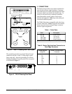
Figure 2. T400 LP Housing with Cover Open
Ground
Lug
Frame
Modular Connector
Terminal
Barrier
Strip
Mounting
Holes
Card Edge
Connector
DRR
DRT
DTT
DTR
TR
TT
RR
RT
81
J1
L1
P1
RJ-48
P1
8 7 2 1
The ground lug provides an external Frame Ground
connection for pins 11 and 27 of the plugin’s gold
finger card edge. Insert the grounding wire into the
housing through the Network portal of the rear panel,
as illustrated in Figure 3.
3. CONNECTIONS
The barrier strip provides screw-down terminals for
network and customer signal interfaces. Customer-
side connections are usually made through the RJ-48
connector which is prewired to the barrier strip. To
connect to the barrier strip, conductors should be
placed beneath the square washer of each screw
terminal and tightened. Table 1 provides cable pair
connections and descriptions.
The T400 LP housing is compatible with other loop-
powered T400 units. Table 2 describes the terminal
barrier strip and circuit card gold finger connector
interface signal assignments.
NETWORK
CUSTOMER
Figure 3. T400 LP Housing Rear Panel