


vii Contents
Contents
Chapter 1 Overview...........................................2
1.1 Introduction .........................................................2
1.1.1 Fast Fiber Converters Module ................... 2
1.1.2 Dual Power Input ....................................... 2
1.1.3 Flexible Mounting ......................................2
1.1.4 Advanced Protection .................................2
1.1.5 Wide Operating Temperature .................... 2
1.1.6 Easy Troubleshooting................................ 2
1.2 Features.............................................................. 3
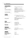
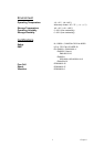
1.3 Specification ....................................................... 4
1.4 Packing List ........................................................ 6
1.5 Safety Precaution ............................................... 6
Chapter 2 Installation........................................8
2.1 LED Indicators .................................................... 8
Table 2.1: EKI-2741F/SX/LX LED Definition.............8
2.2 DIP-Switch .......................................................... 9
Table 2.2: EKI-2741series DIP-Switch Definition........9
2.3 Dimensions (units: mm) .................................... 10
Figure 2.1: Front View of EKI-2741 series.................10
Figure 2.2: Side View of EKI-2741 series ..................11
Figure 2.3: Rear View of EKI-2741 series..................12
Figure 2.4: Top View of EKI-2741 series ...................13
2.4 Mounting........................................................... 14
2.4.1 Wall mounting.......................................... 14
Figure 2.5: Combine the Metal Mounting Kit.............14
2.4.2 DIN-rail Mounting..................................... 15
Figure 2.6: Installation to DIN-rail Step 1...................15
Figure 2.7: Installation to DIN-rail Step 2...................16
2.5 Network Connection ......................................... 17
Figure 2.8: Transceiver to the SFP module .................17
Figure 2.9: Transceiver Inserted..................................17
Figure 2.10: LC connector to the transceiver ..............18
Figure 2.11: Remove LC connector ............................18
Figure 2.12: Pull out from the SFP module.................19
2.6 Power Connection ............................................ 20
Figure 2.13: Pin Assignment of the Power Connector 20
Chapter 3 Troubleshooting ............................ 22
Appendix A Pin Assignment & Wiring ........... 24
Figure A.1: RJ-45 Pin Assignment..............................24
Figure A.2: EIA/TIA-568B .........................................24
Figure A.2: EIA/TIA-568A .........................................24