


vii Contents
Contents
Chapter 1 Overview...........................................2
1.1 Introduction .........................................................2
1.1.1 High-Speed Transmissions ....................... 2
1.1.2 Power-over-Ethernet (PoE) ....................... 2
1.1.3 Dual Power Input ....................................... 2
1.1.4 Flexible Mounting ......................................2
1.1.5 Advanced Protection .................................2
1.1.6 Wide Operating Temperature .................... 2
1.1.7 Easy Troubleshooting................................ 2
1.2 Features.............................................................. 3
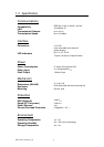
1.3 Specification ....................................................... 4
1.4 Packing List ........................................................ 6
1.5 Safety Precaution ............................................... 6
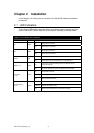
Chapter 2 Installation........................................8
2.1 LED Indicators ....................................................8
Table 2.1: EKI-2525P LED Definition..........................8
2.2 Dimensions (units: mm) ...................................... 9
Figure 2.1: Front View of EKI-2525P...........................9
Figure 2.2: Side View of EKI-2525P ..........................10
Figure 2.3: Rear View of EKI-2525P..........................11
Figure 2.4: Top View of EKI-2525P...........................12
2.3 Mounting........................................................... 13
2.3.1 Wall mounting.......................................... 13
Figure 2.5: Combine the Metal Mounting Kit (units:
mm)..............................................................................13
2.3.2 DIN-rail Mounting..................................... 14
Figure 2.6: Installation to DIN-rail Step 1...................14
Figure 2.7: Installation to DIN-rail Step 2...................15
2.4 Network Connection ......................................... 16
2.5 Power Connection ............................................ 16
Figure 2.8: Pin Assignment of the Power Connector ..16
Chapter 3 Troubleshooting ............................ 18
Appendix A Pin Assignment & Wiring ........... 20
Figure A.1: RJ-45 Pin Assignment..............................20
Figure A.2: EIA/TIA-568B .........................................20
Figure A.2: EIA/TIA-568A .........................................20