PCA-6187 User’s Manual 12
1.8 Jumper Settings
This section provides instructions on how to configure your single board
computer by setting the jumpers. It also includes the single board com-
puter's default settings and your options for each jumper.
1.8.1 How to set jumpers
You can configure your single board computer to match the needs of your
application by setting the jumpers. A jumper is a metal bridge that closes
an electrical circuit. It consists of two metal pins and a small metal clip
(often protected by a plastic cover) that slides over the pins to connect
them. To “close” (or turn ON) a jumper, you connect the pins with the
clip. To “open” (or turn OFF) a jumper, you remove the clip. Sometimes
a jumper consists of a set of three pins, labeled 1, 2, and 3. In this case
you connect either pins 1 and 2, or 2 and 3. A pair of needle-nose pliers
may be useful when setting jumpers.
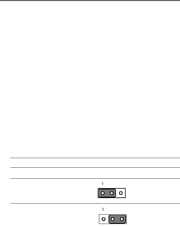
1.8.2 CMOS clear (J1)
The PCA-6187 single board computer contains a jumper that can erase
CMOS data and reset the system BIOS information. Normally this
jumper should be set with pins 1-2 open. If you want to reset the CMOS
data, set J1 to 1-2 closed for just a few seconds, and then move the jumper
back to 1-2 open. This procedure will reset the CMOS to its default set-
ting.
1.8.3 Watchdog timer output (J2)
The PCA-6187 contains a watchdog timer that will reset the CPU or send
a signal to IRQ11 in the event the CPU stops processing. This feature
means the PCA-6187 will recover from a software failure or an EMI
problem. The J2 jumper settings control the outcome of what the com-
puter will do in the event the watchdog timer is tripped.
Table 1.4: CMOS (J1)
Function Jumper Setting
* Keep CMOS data
Clear CMOS data
* default setting
1 -2 closed
2 3 closed


